Home > Textbooks > Basic Electronics > Transformers > Autotransformers >
Transformers
Autotransformers
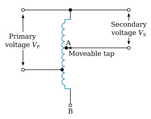
It is not necessary in a transformer for the primary and secondary to be separate and distinct windings. The figure below is a schematic diagram of what is known as an autotransformer. Note that a single coil of wire is "tapped" to produce what is electrically a primary and secondary winding. The voltage across the secondary winding has the same relationship to the voltage across the primary that it would have if they were two distinct windings. The movable tap in the secondary is used to select a value of output voltage, either higher or lower than VP (primary voltage), within the range of the transformer. That is, when the tap is at point A, VS (secondary voltage) is less than VP; when the tap is at point B, VS is greater than VP.