


Home > Textbooks > Basic Electronics > Transformers > Transformer Construction >
Transformers
Transformer Construction
A typical transformer consists of two coils of wire placed on some type of core material. The composition of a transformer core depends on such factors as voltage, current, and frequency. Size limitations and construction costs are also factors to be considered. Commonly used cores are air and soft iron materials (such as steel). Each of these materials is suitable for particular applications and unsuitable for others. Generally, air-core transformers are used when the voltage source has a high frequency (above about 20 kHz). Iron-core transformers are usually used when the source frequency is low (below about 20 kHz). A soft-iron-core transformer is very useful where the transformer must be physically small, yet efficient. The iron-core transformer provides better power transfer than does the air-core transformer. An iron-core transformer whose core is constructed of laminated sheets of steel dissipates heat readily; thus it provides for the efficient transfer of power. The steel laminations (see the figure below) are insulated with a nonconducting material, such as varnish, and then formed into a core. It takes about 50 such laminations to make a core an inch thick. The purpose of the laminations is to reduce transformer losses. An important point to remember is that the most efficient transformer core is one that offers the best path for the most lines of flux with the least loss in energy.
Core-Type Construction
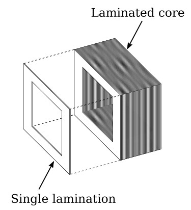
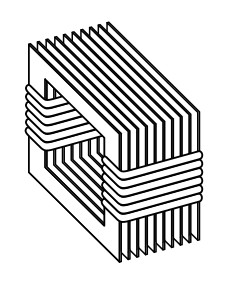
There are two main shapes of cores used in laminated-steel-core transformers. One is the core-type, illustrated in the figure above. Notice that the core is made up of many laminations of steel. The figure below illustrates how the transformer windings are wrapped around both sides of the core.
Shell-Type Construction
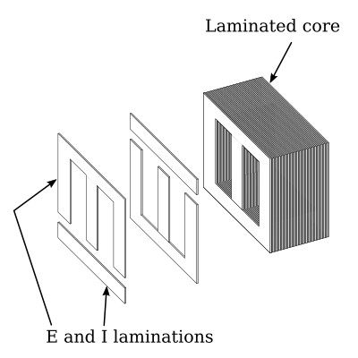
The most popular and efficient transformer core is the shell-type core, as illustrated in the figure below. As shown, each layer of the core consists of E- and I-shaped sections of metal. These sections are butted together to form the laminations. The laminations are insulated from each other and then pressed together to form the core.
The figure below shows an exploded view of a shell-type transformer. The primary winding is wound in layers directly on a rectangular cardboard form.

In the transformer shown in the cutaway view in the figure below, the primary consists of many turns of relatively small wire. The wire is coated with varnish so that each turn of the winding is insulated from every other turn. In a transformer designed for high-voltage applications, sheets of insulating material, such as paper, are placed between the layers of windings to provide additional insulation.
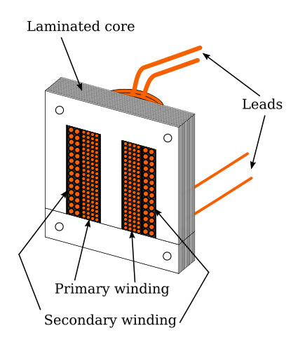
When the primary winding is completely wound, it is wrapped in insulating paper or cloth. The secondary winding is then wound on top of the primary winding. After the secondary winding is complete, it too is covered with insulating paper. Next, the E and I sections of the iron core are inserted into and around the windings as shown.
The leads from the windings are normally brought out through a hole in the enclosure of the transformer. Sometimes, terminals may be provided on the enclosure for connections to the windings. The figure shows four leads, two from the primary and two from the secondary. These leads are to be connected to the source and load, respectively.


