


Home > Textbooks > Basic Electronics > Transformers > Transformer Basics >
Transformers
Transformer Basics
A transformer is a device that transfers electrical energy from one circuit to another by electromagnetic induction. The electrical energy is always transferred without a change in frequency, but may involve changes in amplitudes of voltage and current. Because a transformer works on the principle of electromagnetic induction, it must be used with an input source voltage that varies with time. There are many types of power that fit this description; for ease of explanation and understanding, transformer action will be explained using a sinusoidal AC voltage as the input source.
The Components of a Transformer
In its most basic form a transformer consists of:
- The primary winding (coil), which receives energy from the AC source.
- The secondary winding (coil), which receives energy from the primary winding and delivers it to the load.
- The core, which provides a path for the magnetic lines of flux.
The primary and secondary coils are wound on some type of core material. In some cases the coils of wire are wound on a cylindrical or rectangular non-magnetic form. In effect, the core material is air and the transformer is called an air-core transformer. Transformers used at low frequencies, such as 50 and 60 Hz, require a core of low-reluctance magnetic material, usually iron. This type of transformer is called an iron-core transformer.
Schematic Symbols for Transformers
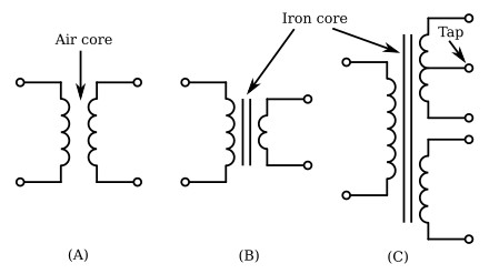
Figure below shows typical schematic symbols for transformers. The symbol for an air-core transformer is shown in view A. Parts B and C of the figure show iron-core transformers. The bars between the coils are used to indicate an iron core. Frequently, additional connections are made to the transformer windings at points other than the ends of the windings. These additional connections are called taps. When a tap is connected to the center of the winding, it is called a center tap. View C of the figure below shows the schematic representation of a center-tapped iron-core transformer.
Transformer Action with No Load
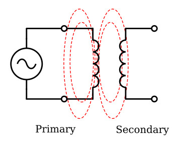
Figure below illustrates an air-core transformer. The primary winding is connected to a sinusoidal AC voltage source. The source voltage drives a current through the primary and, being sinusoidal, undergoes continuous changes in magnitude and direction. The magnetic field (flux) builds up (expands) and collapses (contracts) about the primary winding. The changing magnetic field produced by the primary coil cuts the secondary winding. An induced voltage (EMF) is developed in the primary and secondary windings by the changing magnetic field. The primary induced voltage is slightly less than the source voltage, and they are opposite in polarity to each other. The small difference between the source voltage and primary induced voltage is just great enough to permit the flow of a small primary current, called the magnetization, or excitation, current, when the secondary is not connected to a load.
The amount of excitation current is determined by three factors: (1) the amount of source voltage, (2) the resistance of the primary coil's wire and core losses, and (3) the reactance of the primary coil which is dependent on the frequency of the exciting current. These last two factors are controlled by transformer design.
The excitation current serves two functions:
- Most of the exciting energy is used to maintain the magnetic field of the primary.
- A small amount of energy is used to overcome the resistance of the wire and core losses which are dissipated in the form of heat (power loss).
Primary and Secondary Phase Relationship
The secondary voltage of a transformer may be either in phase or out of phase with the primary voltage. This depends on the direction in which the windings are wound and the arrangement of the connections to the external circuit (load). Simply, this means that the two voltages may rise and fall together or one may rise while the other is falling.
Transformers in which the secondary voltage is in phase with the primary are referred to as like-wound transformers, while those in which the voltages are 180 degrees out of phase are called unlike-wound transformers.
Dots are used to indicate points on a transformer schematic symbol that have the same instantaneous polarity (points that are in phase).
The use of phase-indicating dots is illustrated in figure below. In part (A) of the figure, both the primary and secondary windings are wound from top to bottom in a clockwise direction, as viewed from above the windings. When constructed in this manner, the top lead of the primary and the top lead of the secondary have the same polarity. This is indicated by the dots on the transformer symbol. A lack of phasing dots indicates a reversal of polarity.
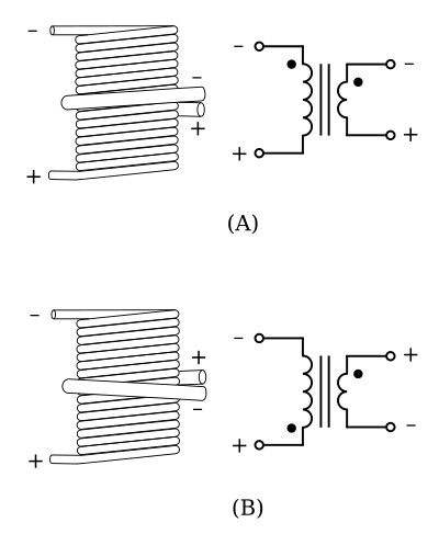
Part (B) of the figure illustrates a transformer in which the primary and secondary are wound in opposite directions. As viewed from above the windings, the primary is wound in a clockwise direction from top to bottom, while the secondary is wound in a counterclockwise direction. Notice that the top leads of the primary and secondary have opposite polarities. This is indicated by the dots being placed on opposite ends of the transformer symbol. Thus, the polarity of the voltage at the terminals of the secondary of a transformer depends on the direction in which the secondary is wound with respect to the primary.
Coefficient of Coupling
The coefficient of coupling of a transformer is dependent on the portion of the total flux lines that cuts both primary and secondary windings. Ideally, all the flux lines generated by the primary should cut the secondary, and all the lines of the flux generated by the secondary should cut the primary. The coefficient of coupling would then be one (unity), and maximum energy would be transferred from the primary to the secondary. Practical power transformers use high-permeability silicon steel cores and close spacing between the windings to provide a high coefficient of coupling.
Lines of flux generated by one winding which do not link with the other winding are called leakage flux. Since leakage flux generated by the primary does not cut the secondary, it cannot induce a voltage into the secondary. The voltage induced into the secondary is therefore less than it would be if the leakage flux did not exist. Since the effect of leakage flux is to lower the voltage induced into the secondary, the effect can be duplicated by assuming an inductor to be connected in series with the primary. This series leakage inductance is assumed to drop part of the applied voltage, leaving less voltage across the primary.
Turns and Voltage Ratios
The total voltage induced into the secondary winding of a transformer is determined mainly by the ratio of the number of turns in the primary to the number of turns in the secondary, and by the amount of voltage applied to the primary. Refer to figure below. Part (A) of the figure shows a transformer whose primary consists of ten turns of wire and whose secondary consists of a single turn of wire. You know that as lines of flux generated by the primary expand and collapse, they cut both the ten turns of the primary and the single turn of the secondary. Since the length of the wire in the secondary is approximately the same as the length of the wire in each turn in the primary, voltage (EMF) induced into the secondary will be the same as the voltage (EMF) induced into each turn in the primary. This means that if the voltage applied to the primary winding is 10 volts, the counter EMF in the primary is almost 10 volts. Thus, each turn in the primary will have an induced counter EMF of approximately one-tenth of the total applied voltage, or one volt. Since the same flux lines cut the turns in both the secondary and the primary, each turn will have an EMF of one volt induced into it. The transformer in part (A) of figure below has only one turn in the secondary, thus, the EMF across the secondary is one volt.
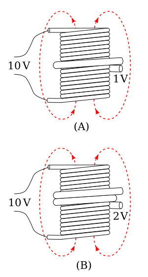
The transformer represented in part (B) of figure above has a ten-turn primary and a two-turn secondary. Since the flux induces one volt per turn, the total voltage across the secondary is two volts. Notice that the volts per turn are the same for both primary and secondary windings. Since the counter EMF in the primary is equal (or almost) to the applied voltage, a proportion may be set up to express the value of the voltage induced in terms of the voltage applied to the primary and the number of turns in each winding. This proportion also shows the relationship between the number of turns in each winding and the voltage across each winding. This proportion is expressed by the equation

where
Np - number of turns in the primary
Vp - voltage applied to the primary
Vs - voltage induced in the secondary
Ns - number of turns in the secondary
Notice the equation shows that the ratio of secondary voltage to primary voltage is equal to the ratio of secondary turns to primary turns. The equation can be written as
![]()
The following formulas are derived from the above equation:

If any three of the quantities in the above formulas are known, the fourth quantity can be calculated.
Example
A transformer has 200 turns in the primary, 50 turns in the secondary, and 120
volts applied to the primary (Vp). What is the voltage
across the secondary (Vs)?
Solution:

The transformer in the above problem has fewer turns in the secondary than in the primary. As a result, there is less voltage across the secondary than across the primary. A transformer in which the voltage across the secondary is less than the voltage across the primary is called a step-down transformer. The ratio of a four-to-one step-down transformer is written as 4:1. A transformer that has fewer turns in the primary than in the secondary will produce a greater voltage across the secondary than the voltage applied to the primary. A transformer in which the voltage across the secondary is greater than the voltage applied to the primary is called a step-up transformer. The ratio of a one-to-four step-up transformer should be written as 1:4. Notice in the two ratios that the value of the primary winding is always stated first.
Effect of a Load
When a load resistance is connected to the secondary winding (figure below), the voltage induced into the secondary winding causes current to flow in the secondary winding. This current produces a flux field about the secondary (shown as broken lines) which is in opposition to the flux field about the primary (Lenz's law). Thus, the flux about the secondary cancels some of the flux about the primary. The total flux in the core of the transformer is common to both the primary and secondary windings. With less flux surrounding the windings, the primary and secondary induced voltages are reduced. A reduction in the primary induced voltage increases the difference between the source voltage and the primary induced voltage, thereby permitting a larger primary current to flow. The additional current in the primary generates more lines of flux, nearly reestablishing the original number of total flux lines.
Turns and Current Ratios
The number of flux lines developed in a core is proportional to the magnetizing force (in ampere-turns) of the primary and secondary windings. The ampere-tum (I × N) is a measure of magnetomotive force; it is defined as the magnetomotive force developed by one ampere of current flowing in a coil of one turn. The flux which exists in the core of a transformer surrounds both the primary and secondary windings. Since the flux is the same for both windings, the ampere-turns in both the primary and secondary windings must be the same.
Therefore:
![]()
where
Ip Np - ampere-turns in the primary winding
Is Ns - ampere-turns in the secondary winding
By dividing both sides of the equation by Ip Ns, you obtain:

Since

then

where
Vp - voltage applied to the primary
Vs - voltage across the secondary
Ip - current in the primary
Is - current in the secondary
Notice the equations show the current ratio to be the inverse of the turns ratio and the voltage ratio. This means, a transformer having less turns in the secondary than in the primary would step down the voltage, but would step up the current.
Example:
A transformer has a 6:1 voltage ratio. Find the current in
the secondary if the current in the primary is 200 mA.
Solution:
Transposing for Is:

Substitution:

The above example points out that although the voltage across the secondary is one-sixth the voltage across the primary, the current in the secondary is six times the current in the primary.
The above equations can be looked at from another point of view. The expression
![]()
is called the transformer turns ratio and may be expressed as a single factor. Remember, the turns ratio indicates the amount by which the transformer increases or decreases the voltage applied to the primary. For example, if the secondary of a transformer has two times as many turns as the primary, the voltage induced into the secondary will be two times the voltage across the primary. If the secondary has one-half as many turns as the primary, the voltage across the secondary will be one-half the voltage across the primary. However, the turns ratio and the current ratio of a transformer have an inverse relationship. Thus, a 1:2 step-up transformer will have one-half the current in the secondary as in the primary. A 2:1 step-down transformer will have twice the current in the secondary as in the primary.
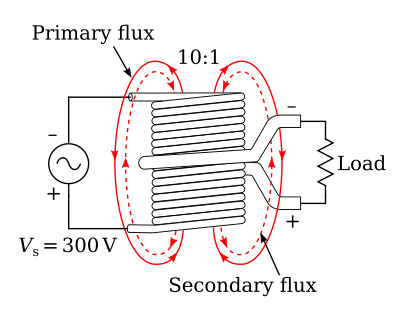
Power Relationship Between Primary and Secondary Windings
As just explained, the turns ratio of a transformer affects current as well as voltage. If voltage is doubled in the secondary, current is halved in the secondary. Conversely, if voltage is halved in the secondary, current is doubled in the secondary. In this manner, all the power delivered to the primary by the source is also delivered to the load by the secondary (minus whatever power is consumed by the transformer in the form of losses). Refer again to the transformer illustrated in figure above. The turns ratio is 10:1. If the input to the primary is 0.1 A at 300 V, the power in the primary is P = V × I = 30 W. If the transformer has no losses, 30 W is delivered to the secondary. The secondary steps down the voltage to 30 V and steps up the current to 1 A. Thus, the power delivered to the load by the secondary is P = V × I = 30 V × 1 A = 30 W.
The important thing to remember is that with the exception of the power consumed within the transformer, all power delivered to the primary by the source will be delivered to the load.
As a formula:
![]()
where
Ps - power delivered to the load by the secondary
Pp - power delivered to the primary by the source
PL - power losses in the transformer


