


Home > Textbooks > Selected Circuits > Wave Shaping > Positive Clipper >
Wave Shaping
Positive Clipper
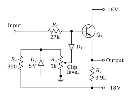
This circuit is composed of a positive clipper followed by an emitter follower. R4 and D2 form a voltage divider between the +18 volts supply and ground. The zener diode (D2) acts as a voltage regulator to maintain a constant voltage across the "clip level" potentiometer R3. As the arm of R3 is moved away from ground, an increasing voltage will be developed at the arm establishing a positive voltage level at the cathode of D1.
The input signal is fed through R1 to the anode of the diode D1. When the voltage at the anode of D1 is positive with respect to its cathode, D1 will conduct, shorting the signal on the base of Q1 at the voltage established at the arm of R3.
Q1 is used as an emitter follower. Its emitter resistor R2 is returned to the +18 volts supply to permit the output signal to go positive with respect to ground. The signal appearing at the output will be essentially the same as that applied to the input except that the clipping action of D1 prevents positive excusions from exceeding the voltage level established by the setting of the "clip level" potentiometer.
