


Home > Textbooks > Selected Circuits > Wave Shaping > RC Integrator >
Wave Shaping
RC Integrator
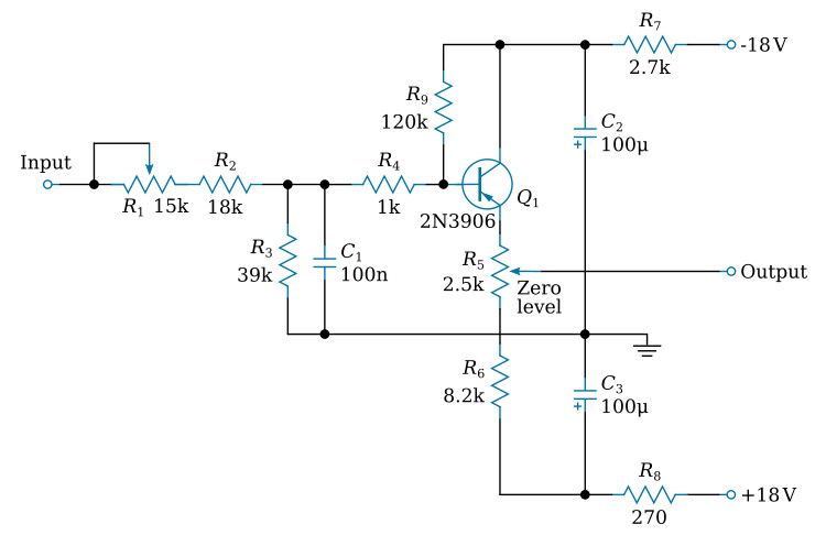
The circuit is composed of RC integrator circuit followed by an emitter follower with an adjustable DC output level control. The RC integrator is made up of the variable resistor R1 and the elements R2 and C1. The sum of the resistance of R1, R2, and C1 represents a long time constant. Because of the high resistance in the charge path of C1, it is not capable of following fast changes and thus tends to integrate the input signal. R3 provides a DC path from the base of Q1 to ground.
Q1 is an emitter follower which is connected between the minus and plus supplies in order to permit both positive and negative output signals. The output of the integrator circuit is fed through R4 to the base of Q1. The emitter is coupled through the variable resistor R5 and through the resistor R6 to the positive supply. By varying the arm of R5, it is possible to change the DC output level with a minimum effect on the AC signal.
R7, C2, and R8, C3 form filtering networks.
