


Home > Textbooks > Selected Circuits > Wave Shaping > Pulse-Width Discriminator >
Wave Shaping
Pulse-Width Discriminator
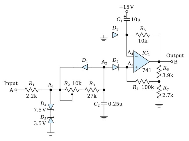
The circuit shown in the figure above prevents short-duration pulses from affecting output B. The normal states for input A and output B are negative voltages supplied by saturated operational amplifiers. In this operating mode, the potential at A1 is approximately -8.2 volts. This value is unaffected by changes in the power supply or the operational amplifiers, since it is maintained by the zener diode circuit. When A becomes positive, A1 changes to +4.2 volts. This shift from -8.2 to +4.2 volts causes A2 and A3 to increase exponentially, since diode D1 blocks the current. When A returns to its normal state, diode D1 conducts and quickly returns A2 to its normal state.
If A remains positive for longer than 10 milliseconds, A3 will build up to a value that is positive with respect to the voltage at A4 and trigger output B to a positive voltage. The positive feedback circuit around the operational amplifier and the blocking action of diode D2 keeps B latched at a positive value even though A2 returns to its normal state. Output B remains positive until A4 increases to a positive value greater than the voltage at A3. One hundred milliseconds are required before B resets to its normal state. When B becomes negative, diode D3 conducts and returns A4 to its normal state. The circuit is then ready to detect another input pulse at input terminal A. The adjustment for setting the minimum detectable pulse width is made with the 10-kilohm trimmer potentiometer (R2).
