


Home > Textbooks > Basic Electronics > A/D and D/A Converters > Binary Weighted DAC >
A/D and D/A Converters
Binary Weighted DAC
In practice many of the DAC circuits make use of the switching of binary weighted resistors. Shown in the figure below is a resistance-switching circuit which can perform the converting operation, if the value of any of the resistors is

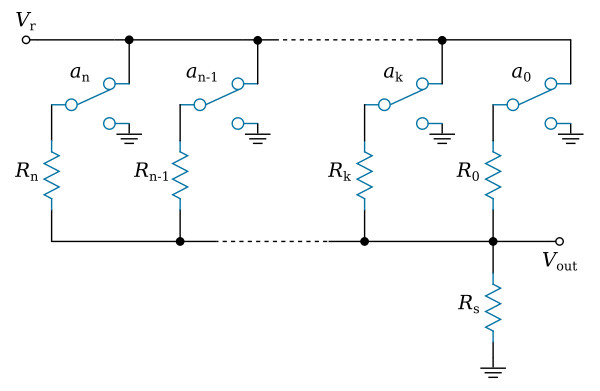
that is, the resistors are binary weighted. Single-pole, double-throw switches are used, and each resistor that is not supplying current from the reference voltage Vr is connected to ground. The switches of this converting circuit represent the binary digits (bits) ak in each position of a binary number. Counting from the left, the first switch represents the most significant digit an and the last switch represents the least significant digit a0. When a certain binary digit ak of the input binary number is a 0, the binary weighted resistor Rk corresponding to this digit is connected in parallel with the summing resistor Rs. When the binary digit ak is a 1, the Rk is connected to the Vr.
The circuit may be analyzed in the following manner. The current, I, flowing from the Vr terminal to ground is I = Vr/R = Vr/(Ra + Rb), where R is the total resistance between the Vr terminal and ground, Ra is the resistance between the Vr terminal and the output terminal, and Rb is the resistance between the output terminal and ground. This current may also be expressed as

where Ga and Gb are conductances with Ga = 1/Ra and Gb = 1/Rb. The output voltage, Vout, is equal to IRb = I/Gb. If I from the above equation is substituted, it is found that

It may now be observed that Ga + Gb = 1/R + 2/R + 4/R + ... or in other words is equal to the sum of the conductances of all of the resistors regardless of the values of the corresponding digits being decoded. This quantity is a constant. However, Ga is the sum of the conductances of those resistors connected to Vr. The result is that Vout is proportional to this sum of conductances.
The above analysis shows that by making the conductances (and not the resistances) proportional to the weights of the binary digits being converted, the output voltage will be proportional to the value of the digital number. Also, it shows that the output voltage varies from zero to Vr, as the digital number varies from 0000... to 1111...
DAC Using a Series Array of Feedback Resistors
Another scheme of the resistor-switching converter is shown in the figure below. This converting device makes use of an operational amplifier in inverting configuration. The feedback circuit is made up of (n + 1) binary weighted resistors, each being shunted by a normally closed switch. The switches are operated by code pulses of a binary number to be converter. If the kth digit ak of the binary number is a 0, the kth switch contact remains closed and the kth resistor remains shorted. If the kth digit is a 1, the switch is opening, thus connecting the kth resistor into the feedback circuit.
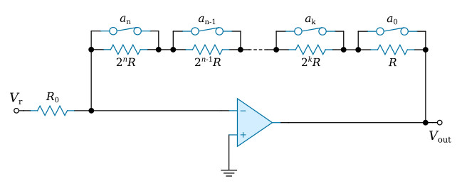
Consequently, following the application of the code pulses of a binary number Nb to this converting circuit, the output voltage will be

where ak = 1 when the switch is opened by a digit 1; ak = 0 when the switch is closed by a digit 0; and

is the value represented by the binary number Nb.


