


Home > Textbooks > Basic Electronics > A/D and D/A Converters > R-2R DAC >
A/D and D/A Converters
R-2R DAC
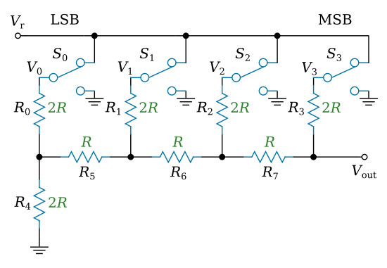
The R-2R DAC is composed of a bank of switches and a resistive network. The figure below shows a diagram of a four digit R-2R DAC. An electric switch is needed for each binary input digit. The switches are opened and closed by the input digital signal, allowing either a reference voltage Vr or ground to be presented to the resistive network. The output of the network is the required analog voltage.
For example, a four switch converter has sixteen possible voltage levels as an output. This is so because the input can be either true or false (logical 1 or 0) and there are four input switches. Hence there are 24 or sixteen, possible input and output combinations. A ten switch converter has 210 or 1024 possible output voltage levels. The greater the number of switches in the converter, the smaller the incremental difference in the output voltage levels.
The resistive network uses just two resistance values, R and 2×R. It can be shown that for a converter consisting of switches S0 to Sn (n + 1 stages), the output voltage is

where Vk is the output voltage of the kth switch (0 or Vr).


