


Home > Textbooks > Basic Electronics > A/D and D/A Converters > Ramp-Type ADC >
A/D and D/A Converters
Ramp-Type ADC
A ramp-type analog-to-digital converter (also known as ramp-compare or time-base ADC) comprises five basic circuits: a ramp generator, a counter, a comparator circuit, a clock pulse generator, and a gate circuit, which are simultaneously operated to provide analog-to-digital conversion. The block diagram of a typical ramp-type ADC is shown in the figure below.
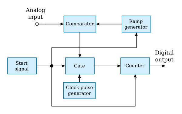
Two inputs are applied to the comparator in the figure above. These are: (1) the analog input, and (2) a linear ramp (sawtooth) voltage from the ramp generator. The generator output is initiated each time a start signal is applied. The start signal also resets the counter to zero and enables the gate circuit.
As long as the analog and ramp generator inputs to the comparator differ in magnitude, the clock pulse generator will be permitted to transmit pulses at a constant repetition rate through the gate into the counter. When the two inputs to the comparator become equal (as a result of the linearly rising sawtooth) the comparator will generate a stop signal which disables the gate circuit and ends the comparison time interval. The disabled gate circuit blocks the flow of pulses from the clock pulse generator to the counter. The number of pulses accumulated in the counter during the comparison time interval is proportional to the amplitude of the analog input voltage. The counter indication is the desired digital representation of the input signal.


