


Home > Textbooks > Basic Electronics > A/D and D/A Converters > Successive-Approximation ADC >
A/D and D/A Converters
Successive-Approximation ADC
The successive-approximation ADC, to be discussed next, is also known as feedback encoder. It uses a digital-to-analog converter (DAC) in a feedback arrangement. The general scheme is outlined in block diagram form shown in the figure below.
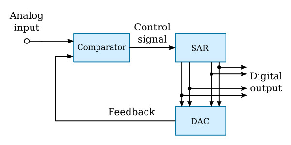
All converters of this class work on the same principle. They make a trial digitization, convert the trial digital number back into analog form, and compare the resulting analog signal with the input signal.
Initially, the digital number in the successive approximation register (SAR) is zero. The SAR then turns on (sets) its most significant bit (MSB). This causes the DAC to deliver to the second input of the comparator a feedback voltage proportional to this bit. The comparator determines whether the feedback voltage is larger than the input signal. If the feedback voltage is larger, the comparator's output tells the SAR to turn off (clear) the MSB; if the feedback voltage is not larger, the MSB remains set. The SAR then sets the next bit, the comparator again determines whether the new feedback voltage is larger than the input signal, and, depending as before on the result of the comparison, this bit is either allowed to remain or is cleared. This process continues until the least-significant bit has been allowed to remain on or is cleared. Each bit that remains on in the SAR represents a logical 1, and those turned off are logical 0's. At the conclusion of the conversion operation the digital representation of the analog voltage is stored in the SAR.


