


Home > Textbooks > Basic Electronics > DC Network Analysis > Branch Current Method >
DC Network Analysis
Branch Current Method
The branch current method is a circuit analysis technique of determining
the current in each branch of a circuit using Kirchhoff's and Ohm's laws.
Note: A branch is a section of a circuit that has a complete path for current.
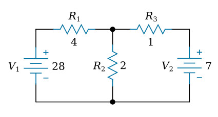
Let's use this circuit to illustrate the method:
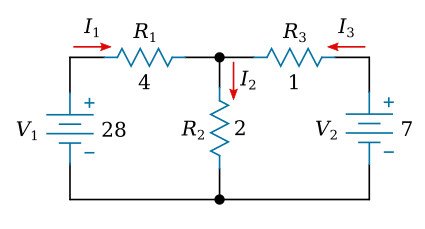
The first step is to assign a current in each circuit branch in an arbitrary (assumed) direction. There are three branches in this circuit and consequently three currents to consider. We will label the three currents as I1, I2, and I3, respectively (see the figure below).
The next step is to apply Kirchhoff's voltage law for each loop of the circuit. In this step, the voltage drops across all resistors are expressed using branch currents and Ohm's law. The directions (from + to -) of the voltage drops across resistors are considered to be equal to the assigned current directions. We can write two such equations for two loops in this circuit.
Left loop (R1, R2, V1):
![]()
Right loop (R2, R3, V2):
![]()
Third step, Kirchhoff's current law is applied to all nodes except the ground reference. The ground reference node is usually the node with most connections. We will choose the bottom node as the reference (see the figure below).
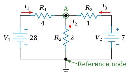
Kirchhoff's current law applied to the top (A) node:
![]()
Fourth and last step is to solve the equations resulting from previous steps for the branch currents.
Solutions:
![]()
Note: Negative sign of I3 means that our assumed direction for I3 is opposite of its real direction.


