


Home > Textbooks > Basic Electronics > DC Network Analysis > Mesh Current Method >
DC Network Analysis
Mesh Current Method
The mesh current method is a circuit analysis technique of determining the current in each branch of a circuit using Kirchhoff's voltage law and Ohm's law. It differs from the branch current method in that it is not necessary to apply Kirchhoff's current law. It is usually able to solve a circuit with less simultaneous equations.
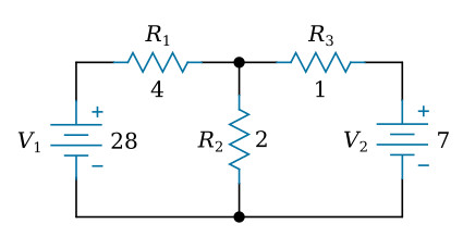
Let's use this circuit to illustrate the method:
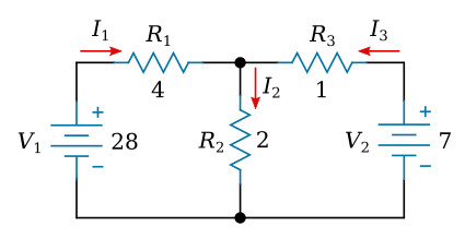
The first step is to assign a current in each circuit branch in an arbitrary (assumed) direction. There are three branches in this circuit and consequently three currents to consider. We will label the three currents as I1, I2, and I3, respectively (see the figure below).
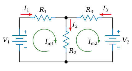
The second step is to draw a mesh current in each loop within the circuit encompassing all components (see the figure below). The choice of each current's direction is entirely arbitrary, in our case it is clockwise direction. In any branch, the actual branch current is the algebraic sum of the mesh currents flowing through that branch. If the direction of a mesh current is opposite to the direction of the branch current, we use the negative sign before this mesh current in the algebraic sum. The branch currents I1, I2 and I3 may be written in terms of mesh currents Im1 and Im2 as
![]()
The next step is to apply Kirchhoff's voltage law for each loop of the circuit. In this step, the voltage drops across all resistors are expressed using mesh currents (instead of branch currents) and Ohm's law. We can write two such equations for two loops in this circuit.
Left loop (R1, R2, V1):
![]()
Right loop (R2, R3, V2):
![]()
The fourth step is to solve the equations resulting from the previous step for the mesh currents.
Solutions:
![]()
The branch currents obtained from these mesh currents:
![]()
Note: Negative sign of I3 means that our assumed direction for I3 is opposite of its real direction.


