


Home > Textbooks > Basic Electronics > AC Circuits > Alternating Voltages and Currents >
AC Circuits
Alternating Voltages and Currents
Introduction
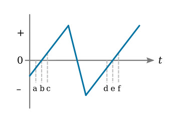
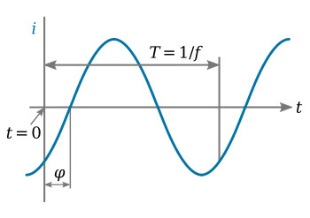
An alternating voltage is any voltage that varies in both magnitude and polarity with respect to time. The voltage may vary in a regular, predictable manner, or the voltage may vary in an irregular, nonrepetitive manner with respect to time. In either case, the voltage is considered to be an alternating voltage. The figure below shows an alternating voltage that varies in a regular manner with respect to time.
An alternating current is any current that varies in both magnitude and direction. As with alternating voltages, there are no limitations on rate of change or waveshape. An alternating current is simply a current that changes magnitude and direction with time.
Alternating currents and voltages are widely used to distribute electric power. However, the uses of alternating voltages and currents extend far beyond the distribution of electric power. All electronic communication systems, electronic computers, and electronic instrumentation systems require alternating currents and voltages as well as direct voltages and currents. When alternating voltages and currents supply electric power to operate other devices, the AC (the notation "AC" is common usage to denote either an alternating voltage or current or both) is usually produced by huge alternators (AC generators) operated by power companies. Electronic devices may also be used to develop AC voltages and currents. In this case, the source of the alternating voltages and currents is a circuit called an oscillator. An oscillator is an electronic circuit that converts DC into AC.
Frequency and Period
DC voltages and currents are easily defined in magnitude. Alternating voltages and currents, however, can not be exactly defined in terms of magnitude only. All alternating voltages and currents have three characteristics: amplitude, frequency, and phase. This section is concerned with the frequency characteristic of AC voltages and currents.
It was stated that any voltage or current that changes polarity or direction is considered to be AC. However, the great majority of all AC voltages and currents change in magnitude and direction at predetermined rates. That is, an AC voltage rises to a maximum value, decreases from maximum to zero, then rises to maximum value of the opposite polarity, and again decreases to zero. It repeats this process continuously.
A cycle of alternating voltage or current consists of one complete transition from some point on an AC waveform to the same point on the following AC waveform. For example, one cycle of the AC waveform of the figure above may be measured between points a and d, b and e, or c and f.
The number of cycles per second is defined as the frequency of an AC voltage or current. For example, common power-line frequency in the United States is 60 cycles per second (cps), while the frequency of a radio broadcasting station may be 106 cps. Television stations operate at frequencies on the order of 108 cps.
Some fundamental mathematical relationships can now be written relating frequency to the time of one cycle. Since frequency equals cycles per second, it follows that

where
T - time of one cycle (period), sec
f - frequency, cps or hertz (Hz)
When the time of one cycle is known, frequency is found by

Sinusoidal Voltages and Currents
A unique waveform for AC voltage or current is the sine wave. In preceding sections, it has been stated that an alternating voltage or current may have any waveshape. This is indeed true, but this very fact could make mathematical analysis of alternating-current circuits very laborious. However, it can be shown mathematically and demonstrated graphically that any waveshape, no matter how irregular, consists of various combinations of sinusoidal waveshapes. Therefore, the unique feature of the sine wave is that it is basic to all AC voltages and currents!
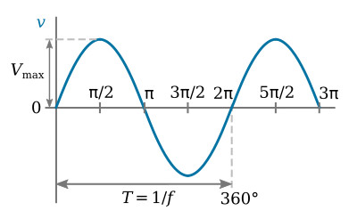
In the sine wave, one complete cycle is represented by 360° or 2π radians. Hence, if the period of a sine wave is 0.2 s, then each degree of the cycle represents 0.556 ms. At any instant, the instantaneous value of the sine wave equals the product of the maximum value of the sine wave and the sine of the angle corresponding to time. The equation for a sine wave of voltage is
![]()
where θ is any angle.
The equation for a sine wave of current is written in a similar manner.
![]()
The figure below is a sine wave of voltage, showing the substitution of angular measure in degrees and radians for time.
In addition to the graphic representation of a sine wave, like that in the figure above, a sine wave may be represented by a radius vector, or phasor.
The phasor has a constant magnitude equal to the maximum value of the sine wave, and the instantaneous value of the sine wave is the product of the phasor and the sine of the angle between the phasor and the origin. The phasor representation is extremely useful in adding and subtracting alternating voltages and currents. The figure below illustrates phasor representation for the sine wave of figure above.
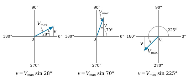
Discussion of phasor representation of sine waves leads logically to another useful concept. Angular velocity is normally associated with rotating machinery. However, a phasor representing a sine wave may be visualized as rotating vector, and as such it too has angular velocity. As indicated in the figure above, the positive direction of rotation is counterclockwise (ccw).
Velocity is the ratio of distance to time. The angular velocity of a sine wave is the "distance" of one cycle, in radians, divided by the period of the sine wave. Angular velocity is represented by lowercase omega (ω).
![]()
However, T = 1/f. If this value of T is substituted into the above equation, then
![]()
Equations for the sine wave of voltage and sine wave of current may be rewritten in terms of the above equation. The angular velocity of a sine wave is a constant, and the particular angle of a sine wave at any instant is a direct function of time. Hence, if the angular velocity is multiplied by time in seconds, the product is an angle in radians.
![]()
Equations for the sine wave of voltage and sine wave of current, when radian measure is used, are written

Phase Angle and Phase Difference
It was noted that all AC voltages and currents have three characteristics; frequency, amplitude, and phase. In this section, the phase characteristics of a sine wave will be discussed.
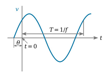
In the equation of a sine wave, the independent variable is time. In both representations of the sine wave, by graph or by phasor, an angular notation has been substituted for time. It should be apparent from the equation of the sine wave that all sinusoids have zero value at the time that the angular equivalent of time is zero. It is conventional to represent a sine wave as starting at 0°. However, it is equally permissible to consider a sine wave as starting at any other point on its cycle. The figure above illustrates a sine wave of voltage that is not zero at the start of its cycle.
When a sine wave is considered to start at some magnitude other than zero, the fact must be indicated in the equation of the wave. The angular displacement of a wave from 0° to the point on its cycle where the wave is considered to begin is its phase angle. For example, in the figure above θ is the phase angle of the wave.
The equation for the voltage waveform of figure above is written
![]()
The figure below illustrates a sine wave of current described by the equation
![]()
In AC circuits that contain capacitance, inductance, or both, the phase angles of current and voltage can differ from one another. That is, the current in the circuit may reach maximum or minimum at different times than the voltage. This time difference between alternating quantities is called phase difference and is expressed in degrees. Phase difference may also express the time displacement between waves of different frequencies that are present in the same circuit.
It should be apparent that the phase difference between sine waves of different frequencies is constantly changing. However, it is often convenient to express the phase difference between signals of different frequencies at some particular instant in time. When alternating quantities of the same frequency reach positive maxima (or any other convenient reference point on the cycle) at the same instant, the quantities are said to be in phase: the phase difference between them is 0°.
The figure below shows two phasors of the same frequency displaced from each other by θ°. v1 is said to be leading v2 by θ° (counterclockwise rotation of phasors, as noted earlier, is the positive direction).
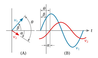
The equations for voltages v1 and v2 in the figure above are

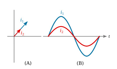
Note that the phase difference between v1 and v2 is the sum of angles β and α. It may be stated that v1 leads the reference axis by β degrees, and v2 lags this same reference by α degrees. The figure below illustrates two currents that are in phase with each other. Part A is the phasor representation of these currents, and Part B shows the currents as sinusoids.
The Average Value of a Sine Wave
The average value of any current or voltage is the value that would be indicated by a DC meter. This concept is of particular value in electronics, since many voltages and currents are combinations of DC and sinusoids. The concept of average values is of particular importance in rectifier circuits.
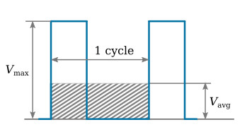
The average value of any curve is the area enclosed by the curve divided by the base of the curve. The figure below shows one cycle of a rectangular pulse of voltage, and it illustrates the average value of this pulse over one cycle.
It is apparent that the average value of a sine wave over a complete cycle is zero, since the average of one half of the cycle is exactly equal but opposite in polarity to the average of the other half. The average value of a sine wave is usually obtained by assuming that it has been rectified. That is, both halves of the waveform are assumed to be positive. A rectified sine wave is shown in the figure below.
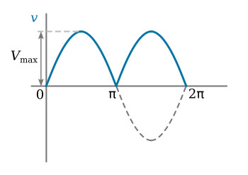
Calculation of the average value of a sine wave is accomplished with the integral calculus. This process yields the average value of the curve from 0 to π radians. This average value is also that of the sine wave over a full cycle and it is frequently referred to as the average rectified value. The average rectified value of voltage is
![]()
The average rectified value of a sine wave of current is
![]()
The Effective Value of a Sine Wave
The effective value of a current or voltage waveform is that value that will dissipate the same power as a numerically equal DC current or voltage. For example, an AC current of 2-amp effective value dissipates exactly the same power as 2-amp DC. Note that no consideration is given to the waveshape of the AC current; we simply state that an effective current of 2-amp AC develops the same power as 2-amp DC. In short, the effective value is defined in terms of power dissipation.
The effective value is frequently referred to as the root-mean-square (rms) value. The effective values of a sine wave are

Note that lowercase letters are used to indicate instantaneous values of current or voltage whenever the current or voltage is variable with time. Definite values of current or voltage are indicated with capital letters (Vmax, Imax, etc.).


