


Home > Textbooks > Basic Electronics > AC Circuits > Series RLC Resonant Circuit >
AC Circuits
Series RLC Resonant Circuit
It was shown that inductive reactance is directly proportional to frequency, while capacitive reactance is inversely proportional to frequency. Since inductive reactance and capacitive reactance are in opposition to each other, it can be seen that a circuit containing both inductance and capacitance will have an impedance that varies with frequency. The circuit containing inductance and capacitance appears capacitive over one range of frequencies and inductive at other frequencies. At some frequency, the reactances will exactly balance one another and the circuit will appear purely resistive. The frequency at which an RLC circuit appears as a net resistance is referred to as the resonant frequency. The frequency-dependent properties of the RLC circuit can be used to select wanted signals or reject unwanted signals on the basis of frequency. Tuning circuits, filter circuits, and a number of other types of circuits employ the properties of resonant circuits.
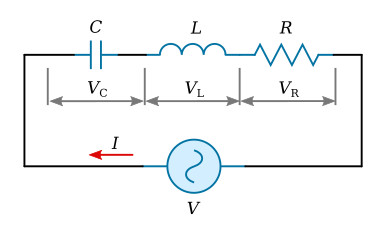
R, L, and C are connected in series as shown in the figure above. The Kirchhoff voltage-loop equation is
![]()
Since current I is the common factor,

In order for the voltage phasor in the above equation to be at 0°, the sum of the reactive drops must equal zero.
![]()
and ![]()
Therefore ![]()
The above equation states that when the inductive and capacitive reactance of the series-RLC circuit are equal, the circuit appears purely resistive. When the series-RLC circuit appears purely resistive, the circuit is said to be in series resonance.
The frequency at which series resonance occurs can be determined from the previous equation as a function of the reactive components L and C. The series-resonant frequency fr is derived in the following manner.

The above equation can be used to determine the resonant frequency if the elements of the series circuit are known. This is demonstrated in Example 1.
Example 1: The elements in the circuit of figure above are: L = 8 mH, C = 0.5 nF, R = 500 Ω, and V = 300∠0° V. Find (1) the resonant frequency, (2) the current, and (3) the voltage across each component.
Solution:
1. Using the above equation,

2. The sum of the reactive voltages is zero at resonance. Therefore,

3. The voltage across each component can now be calculated using the common current of Step 2.

It can be seen from Step 3 of Example 1 that the voltage drop across the inductance and the capacitance is larger than the applied voltage V. The energy supplied by the source is dissipated by the resistance, while the capacitance and the inductance simply exchange energy.
At the resonant frequency, the impedance of a series-RLC circuit is purely resistive and at a minimum. The current is therefore maximum at resonance. As frequency is reduced below resonance, the capacitive reactance increases and the inductive reactance decreases. The net reactance at frequencies below resonant frequency is capacitive, and it increases in magnitude as the frequency is further reduced below the resonant frequency.
The impedance of a circuit below resonance is the phasor sum of the resistance and the net capacitive reactance. Since the reactive component of the circuit is capacitive, the current leads the applied voltage by an increasing angle as the frequency is decreased. The magnitude of the current decreases as the frequency is decreased below resonance.
If frequency is increased above the resonant frequency, the inductive reactance increases and the capacitive reactance decreases. The net reactance above the resonant frequency is inductive, and it increases in magnitude as the frequency increases. Impedance increases and current decreases as the frequency increases above resonance. The current lags the applied voltage by an increasing angle as the frequency is increased above the resonant frequency.


