


Home > Textbooks > Basic Electronics > AC Circuits > Resistance in AC Circuits >
AC Circuits
Resistance in AC Circuits
Introduction
Generally, the waveforms for the alternating voltages and currents of a number of electronic devices do not differ appreciably from a sinusoid. Further, the nonsinusoidal waveforms can be separated into sinusoids for purposes of analysis. Therefore, in all discussion of voltages and currents in the next sections, the sinusoid will be used as the basis of mathematical analysis.
In following sections, the effects of the properties of the electric circuit will be examined. These circuit properties, or circuit parameters, are resistance, inductance, and capacitance. It must be pointed out that it is impossible to construct a purely resistive, purely inductive, or purely capacitive circuit. In discussing pure resistance, pure inductance, or pure capacitance, we are considering hypothetical circuits.
The Pure Resistance Circuit
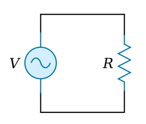
A sinusoidal voltage is applied to a resistance as shown in the figure above.
The resulting time variations in the current and voltage waveforms are shown
in the figure below. From these waveforms, the following can be concluded:
1. Both waves are sinusoidal and have the same frequency.
2. The waves are in phase.
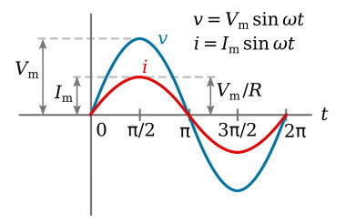
The waveform relations of the figure above can be expressed mathematically. The voltage applied to the resistance of the pure resistance circuit is
![]()
Applying Ohm's law at any instant,

where

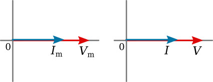
The figure below shows two phasor diagrams. In one the current phasor and voltage phasor are shown as maximum values. In the other, they are shown as effective values. Since these revolving time phasors represent sinusoids, it would be more proper to use maximum values. In practice, it is more convenient to use effective values, and furthermore, the effective values are those that would be indicated by traditional meter readings.
Ohm's law can thus be applied to the effective magnitudes of the phasor current and phasor voltage. Conductance G can be used in the Ohm's-law equations for the phasor current and voltage just as it is in DC circuits.
To demonstrate the Ohm's-law relations of AC current and voltage to a resistance the following example is given.
Example 1: The voltage applied to the resistance of the pure resistance circuit is v = 150 sin 377t. The resistance is 800 Ω. Calculate (1) the maximum value of current, (2) the instantaneous current at t = 0.002 s, and (3) effective value of current.
Solution:
1.

2. Calculating the instantaneous voltage when t = 0.002 s,

The instantaneous current is

The instantaneous current can also be calculated directly

3.

Also
![]()
The average power dissipated in a resistance is given by the equation
![]()
In this equation, voltage and current are given as effective values. It should be noted here that V and I indicate effective values of AC voltage and current, respectively, unless they are subscripted to indicate maximum or average values. Cos θ is the power factor, and θ is the phase angle between current and voltage. Since in a pure resistance circuit the current and voltage are in phase, the angle θ = 0 and the cos θ = 1. The previous equation therefore reduces to the equation for a purely resistive circuit
![]()


