Home > Textbooks > Basic Electronics > AC Circuits > Complex Numbers in Electronics >
AC Circuits
Complex Numbers in Electronics
This section is presented with the intent of supplying the student with mathematical tools that will ease the study of advanced AC circuits. A carpenter could build a house with only a hammer and hand saw for tools. But, it would be foolish for him/her to do so when there are so many labor saving devices, such as power saws, available. Advanced AC circuits could be analyzed by long and laborious calculations. Fortunately this is not necessary because mathematics provides labor saving devices. Some of these, such as complex numbers, j operator, polar notation, etc., will now be discussed.
The j Operator
The j operator rotates a quantity through an angle of 90° counterclockwise (ccw). The j operator, also called the complex operator, is the square root of -1 (√-1). In some texts i is used to denote √-1, but this notation is avoided in electronics because of possible confusion with instantaneous current.
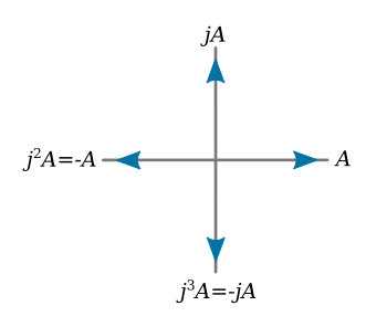
If a magnitude A is located on a set of coordinate axes as shown in the figure above, jA is 90° ccw, j2A is 180° ccw, j3A is 270° ccw, and j4A is 360° ccw. This exponential progression is shown in the table below
| j = √-1 | 90° ccw |
| j2 = -1 | 180° ccw |
| j3 = -j | 270° ccw |
| j4 = +1 | 360° ccw |
With the j operator any quantity can be located on a complex plane with a plus and minus j axis. The complex plane is shown in the figure below.
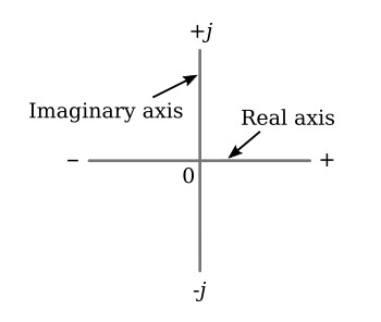
The horizontal axis is referred to as the real axis, and the vertical axis is referred to as the imaginary axis.
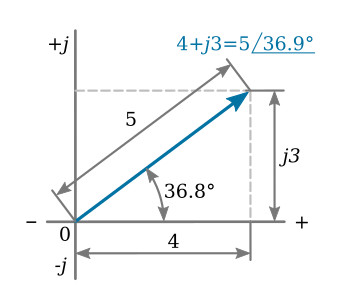
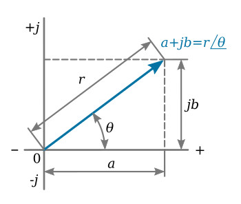
Quantity j3 would be located three units from the origin in the j, or vertical, direction. Quantity a + jb is a general complex number, where a represents a magnitude on the horizontal axis, or the real portion of the complex number, and b represents a magnitude on the vertical axis, or the imaginary portion of the complex number. A quantity represented by 4 + j3 would then be plotted as shown in the figure above. This complex number can also be defined by giving the magnitude of the radial distance r from the origin of the complex plane to the point 4 + j3 and the angle between this radius and the positive real axis. The complex number 4 + j3 can then be given by

and

Thus,
![]()
Consider the general complex number a + jb. The reference angle θ is

and

Thus,
![]()
For this complex number, a + jb is called the rectangular form, while r ∠θ is called the polar form. If a complex number is given in polar form, its rectangular form can be found:

The general equation for converting from polar to rectangular form is
![]()
Boldface A indicates a phasor quantity having both magnitude and direction.
The general equations for converting from rectangular to polar form are


These general relations are shown in the figure below.
Example 1: Given the following complex numbers, convert those in polar form to rectangular form and those in rectangular form to polar form. (1) 300 - j175, (2) -40 + j60, (3) 40∠-45°, (4) 200∠150°.
Solution:

Complex numbers may be added, subtracted, multiplied, or divided. Two or more complex numbers must be added or subtracted in rectangular form:

Complex numbers may be multiplied in either polar or rectangular form. However, it is most conveniently done in polar form.
Multiplying,

Dividing,

It must be noted that a complex number has the following special forms:

Use of Complex Numbers in Electronics
If complex numbers are used to describe sinusoidal currents and voltages, the mathematics of complex numbers can be applied to AC currents and voltages.
If an AC voltage is given by V = V ∠θ (resistance does not cause a phase shift) the current phasor through a resistance would be

where the magnitude of I is

and the phase angle between current and voltage is zero.
This approach can be applied to the purely inductive circuit.
The voltage applied to a purely inductive circuit is
![]()
where γ is any angle.
Apply Ohm's law, using complex notation:

where the magnitude of I is

and the phase angle shows the current to be lagging the voltage by 90 degrees. Therefore the effect of inductive reactance is given by the complex number
![]()
Repeat this process for the purely capacitive circuit. Apply the following voltage to a purely capacitive circuit:
![]()
where γ is any angle.
Applying Ohm's law, using complex notation,

where the magnitude of I is

and the phase angle shows the current leading the voltage by 90 degrees. Therefore the effect of capacitive reactance is given by the complex number

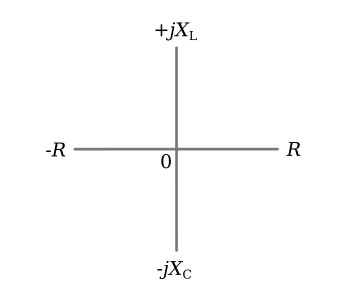
Plotting resistance, capacitive reactance, and inductive reactance on a complex plane yields the results shown in the figure below.
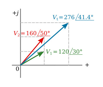
The complex notation is useful in adding and subtracting sinusoidal currents and voltages in phasor form.
To calculate the sum of two voltages given in phasor form by

the voltages must be converted to rectangular form. Therefore,

Adding,
![]()
The sum may then be slated in phasor form:
![]()
This relationship is shown graphically in the figure below.
Example 2: Voltage V = 150 ∠40° volts is applied to a purely capacitive circuit. The frequency of the applied voltage is 15 kHz and the capacitance is 0.06 μF. (1) Calculate the current phasor. (2) Sketch the current and voltage phasors on a complex plane. (3) Write the periodic functions for current and voltage.
Solution:
1.

Note that regardless of the phase angle of the voltage, the current leads the voltage by 90 degrees.
2. See the figure above.
3.

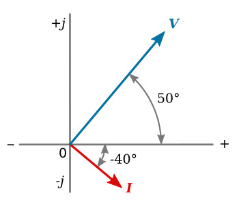
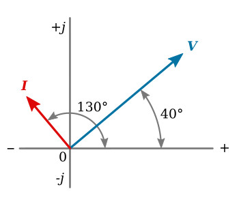
Example 3: Current I = 0.45∠-40° flows in a purely inductive circuit having 780 ohms inductive reactance. Calculate the phasor voltage and sketch the current and voltage phasors on the complex plane.
Solution:
![]()