


Home > Textbooks > Basic Electronics > AC Circuits > Inductance in AC Circuits >
AC Circuits
Inductance in AC Circuits
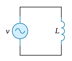
The Pure Inductance Circuit
Inductance was defined as the property of a circuit to oppose change in current. This opposition results in induced EMF. The induced EMF is proportional to the rate at which current is changing as well as the magnitude of the inductance. This relationship can be given by the equation

If a sinusoidal current is flowing in the inductance shown in the figure below, the induced voltage across the inductance can be plotted versus time.
The plot of current in the figure below increases from time t0 to t1. The current is increasing at a decreasing rate, and at time t1 the instantaneous rate of change of current is zero. Therefore, vL is zero at time t1. From time t1 to t2 the current is decreasing; the rate of change of current is negative and vL is negative. At time t2, the rate of change of current is maximum, and thus vL is maximum in the negative direction. At time t3, the rate of change of current is zero, and thus vL is again zero. From t3 to t4, the current is increasing, the rate of change is positive, and vL is positive, reaching maximum at t4, where the rate of change is maximum.
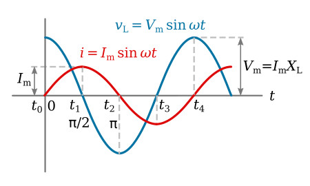
The maximum positive value of voltage occurs 90° ahead of the maximum positive value of current. The current is said to be lagging the voltage by 90 degrees. This phase relationship can be derived mathematically by applying the calculus.
From the previous equation, which is
where
![]()
by differentiation, di/dt is found.

but
![]()
Therefore
![]()
By the general form of a periodic function (i.e. Vm sin (ωt + θ)),
![]()
and

Since the ratio of volts to amperes is defined as opposition to current in ohms, the quantity ωL is measured in ohms. The quantity ωL is called the inductive reactance and is symbolized XL
![]()
If Vm = 1.414 V and Im = 1.414 I are substituted into the equation ωL = Vm / Im, it is seen that the ratio of the effective values of voltage and current also equals the inductive reactance

The reciprocal of inductive reactance is called inductive susceptance and is given the symbol BL. The unit of inductive susceptance is the mho (or siemens S) when the frequency is in hertz and the inductance is in henrys.

Example 1: An AC current with a frequency of 2 kHz and a maximum value of 0.15 A flows in a coil having 175 mH inductance. (1) Find the maximum voltage developed across the inductance. (2) Find the effective value of the voltage across the inductance. (3) Write the periodic functions representing the voltage and current.
Solution:
1.

2.
![]()
The effective value of the voltage can also be found by first calculating the effective value of the current
![]()
Then

3. If the current is taken as the reference,
![]()
The voltage is leading the current in an inductive circuit

Example 2: A voltage across an inductance is 40 V when the current is 120 mA. The frequency of current and voltage is 400 Hz. Find the inductance.
Solution: The magnitude of the inductive reactance can be found

The inductance can now be calculated.

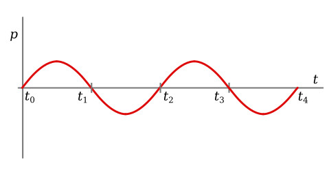
The power relationship in an inductive circuit can be analyzed by writing the equation for power with instantaneous values
![]()
Applying this equation to the figure above, we see that the instantaneous power is positive from t0 to t1, negative from t1 to t2, positive from t2 to t3, and negative from t3 to t4. The instantaneous power is plotted in the figure below. Positive power indicates that energy is taken from the source, and negative power that energy is returned to the source. Since over one complete cycle, from t0 to t4, as much energy is returned as is taken from the source, the net energy taken from the source is zero. Power over a complete cycle is therefore zero. This supports the definition that inductance is the property of a circuit to store energy in the form of a magnetic field. Thus, when current is increasing in magnitude, the magnetic field is building up and storing energy from the source. When current is decreasing in magnitude, the magnetic field is collapsing and returning energy to the source.
The net power is also given by the equation P = VI cos θ:
![]()


