


Home > Textbooks > Basic Electronics > AC Circuits > Series RC Circuit >
AC Circuits
Series RC Circuit
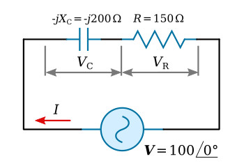
Resistance and capacitive reactance.
In the circuit of figure above, a capacitor and a resistor are shown in series. The current is calculated

The reactive component of the circuit of figure above is capacitive, so the current can be expected to lead the applied voltage by some angle. As shown by the phasor calculation, the angle of lead is 53.1°. The phase relation of applied voltage V and the current is illustrated in the figure below.
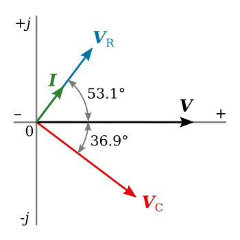
Phasors of the series RC circuit.
Calculating VR and VC,

Applied voltage V must be the phasor sum of VR and VC:

Plotting VR and VC on the complex plane of figure above shows that VR and I are in phase, and that I leads VC by 90°.


