


Home > Textbooks > Basic Electronics > AC Circuits > Parallel RC Circuit >
AC Circuits
Parallel RC Circuit
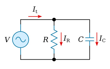
Parallel RC circuits may be resolved in much the same way as are parallel RL circuits. The figure above illustrates a parallel RC circuit.
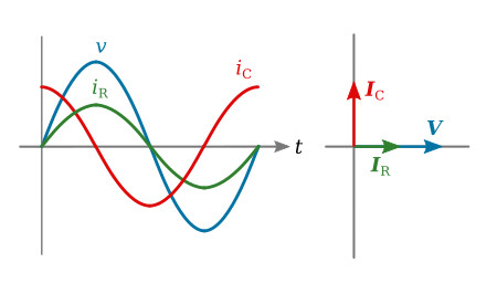
The figure below shows a composite diagram of the circuit conditions. The current phasors IR and IC are out of phase, therefore, phasor addition must be used to determine total current. The solving of an RC circuit follows the method previously applied to LR circuits.
Example 1. The circuit of figure above contains a 36 ohm resistor in parallel with a 6 microfarad capacitor. Both connected across a 25 volt source operating at a frequency of 1.46 kHz. Solve for the following: XC, IR, IC, It, Zt, θ, P.
Solution: Determine the reactance of capacitor XC:


Determine current in branch one (IR):

Determine current in branch two (IC):

Total current may now be determined either graphically or mathematically. The figure below illustrates the graphical method. The results show that It is approximately 1.5 A and It is leading V by an angle of approximately 63°.

It can be determined mathematically by use of the following equations. In a parallel circuit, the sum of the phasors of the currents must equal the total current phasor.
For the parallel RC circuit

This value agrees very closely with the approximation made from the phasors.
Determine total impedance:

Determine the real power dissipated by the circuit:

The equations and method of solving a parallel RC circuit can be seen to be similar in many respects to those used in RL parallel circuits. The phasor diagram of the figure above sums up the circuit just described. The only major difference between the RC phasor diagram and an RL phasor diagram is the angles the reactive component phasors (IC, IL, etc) and the resultant phasors (Zt, It, etc.) assume in respect to the standard position.


