


Home > Textbooks > Basic Electronics > AC Circuits > Capacitance in AC Circuits >
AC Circuits
Capacitance in AC Circuits
The Pure Capacitance Circuit
A change in voltage across a capacitor results in a current that is proportional to both the rate of voltage change and the capacitance. The relations are given by the equation

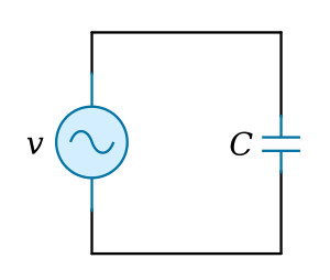
A sinusoidal voltage is applied to a capacitor in the circuit of the figure above. The current is plotted versus time with reference to voltage v in the figure below.
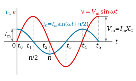
The plot of voltage in the figure above increases from t0 to t1. The voltage is increasing at a decreasing rate, and at t1 the rate of change of voltage is zero. At time t1, the current must then be zero. From time t1 to t2, the voltage is decreasing, and at t2 the voltage is changing at a maximum rate. The current is negative from t1 to t3 and maximum negative at t2. At t3, the rate of change of voltage is instantaneously zero, and therefore the current is zero. From t3 to t4, the voltage is increasing at an increasing rate, and maximum instantaneous rate of change occurs at t4. Therefore i is maximum at t4.
From the waveforms of figure above, it is seen that the maximum positive current occurs 90 degrees ahead of the maximum positive voltage. The current is said to be leading the voltage by 90° in a purely capacitive circuit. This phase relationship is derived mathematically by applying the calculus.
Using the equation
and
![]()
By differentiation, dv/dt is found.

Therefore,

By the general form of a periodic function,

and

Since the ratio of volts to amperes is defined as opposition to current in ohms, the quantity 1/ωC is in ohms. The quantity 1/ωC is called capacitive reactance and is symbolized XC.

XC can be shown to be the ratio of effective values of current and voltage in the same manner as was shown for XL in the previous section.

The reciprocal of capacitive reactance is called capacitive susceptance and is symbolized BC. The unit of capacitive susceptance is the mho (or siemens S) when the frequency is in Hz and the capacitance is in farads.

Example 1: A voltage having an effective value of 220 volts and a frequency of 20 kHz is applied to an 0.08-μF capacitor. (1) Calculate the effective value of the current. (2) Calculate the maximum value of the current. (3) Write the periodic functions representing current and voltage.
Solution:
1.

2.
![]()
3. If the voltage is taken as a reference,
![]()
The current leads the voltage by 90° in a capacitive circuit.
![]()
These periodic functions can also be written with reference to the current.
![]()
With reference to the current, the voltage lags by 90°.
![]()
Example 2: When 250 volts is applied to a 0.05μF-capacitor, a current of 0.6 A is measured. Find the frequency.
Solution: The magnitude of XC can be found.

The frequency can now be calculated from

The power relation in a capacitive circuit can be analyzed with the equation P=VI on the basis of instantaneous values. The product of v and i of the figure above is plotted in the figure below. This is the same as was done in the preceding section for instantaneous power in a pure inductive circuit. The net power in a purely capacitive circuit is zero, as it was in the purely inductive circuit.
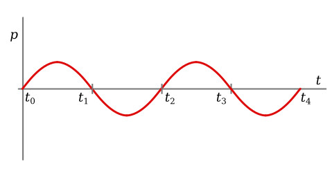
This relationship is justified by considering that from t0 to t1 the voltage is increasing, charge is being stored, and energy is being stored by the capacitor. From t1 to t2, the voltage is decreasing, charge is returned by the capacitor, and energy is returned to the source.
The net power is again given by the equation P = VI cos θ
![]()


