


Home > Textbooks > Basic Electronics > AC Circuits > Parallel LC Resonant Circuit >
AC Circuits
Parallel LC Resonant Circuit
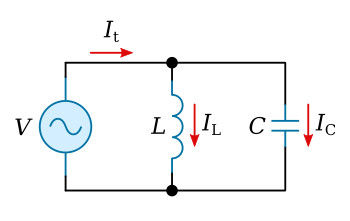
The ideal parallel resonant circuit is one that contains only inductance and capacitance. Resistance and its effects are not considered in an ideal parallel resonant circuit. One condition for parallel resonance is the application of that frequency which will cause the inductive reactance to equal the capacitive reactance. The formula used to determine the resonant frequency of a parallel LC circuit is the same as the one used for a series circuit.

where:
fr - resonant frequency
L - inductance
C - capacitance
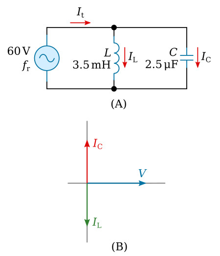
Example: If the circuit values are those shown in the figure above, the resonant frequency may be computed as follows:

At the resonant frequency:
Determine XL:

Determine XC:

Determine IL:

Determine IC:

The total current is determined by addition of the two currents in rectangular form:
![]()
Therefore, in an ideal resonant parallel circuit the total current (It) is zero. If total current is zero then:

or: it may be said that the impedance approaches infinity.
At frequencies other than the natural resonant frequency of the circuit, XC will not be equal to XL and some amount of current will be drawn from the source. If the applied frequency is lower than the resonant frequency of the circuit, XL will be smaller than XC and a lagging source current will result. When the applied frequency is above the resonant frequency, XC is smaller than XL and the source current leads the source voltage.


