


Home > Textbooks > Basic Electronics > AC Circuits > Parallel RL Circuit >
AC Circuits
Parallel RL Circuit
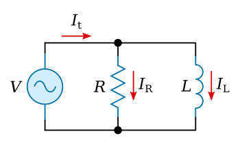
In some respects the circuit of figure above is similar to the purely inductive parallel circuit.
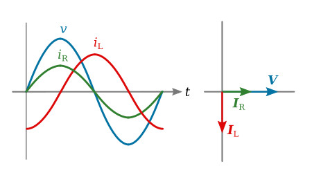
For instance, applied voltage V is still the quantity which is common to both components and is therefore plotted in standard position in the phasor diagram. Also the magnitude of the individual branch currents is determined by the opposition (reactance) of the individual branches. The figure below shows a composite diagram of waveforms and phasors. Since the phasor diagram shows that the two branch currents are not in phase, it will be necessary to use phasor addition in order to determine the total current.
Example 1. Determine the phase angle, Zt, It, IR, IL, P in a parallel RL circuit containing a 1.4 mH coil, a 25 Ω resistor, and a 10 V source operating at 4 kHz.
Solution: Determine the reactance of coil XL:
![]()
![]()
Determine current in branch one (IR):


Determine current in branch two (IL):


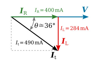
Total current may now be determined either graphically or mathematically. If a phasor diagram is constructed to scale, a very close approximation of values and angles may be obtained. To verify this It will be determined by both methods.
The figure below illustrates the graphical method. The results show that It is approximately 490 mA and It is lagging V by an angle (θ) of approximately 36°.
The phasor diagram approximation may be satisfactory for many applications. For applications requiring greater accuracy It can be determined by use of the following equations.
In a parallel circuit, the sum of the phasors of the currents must equal the total current phasor.
For the parallel RL circuit
![]()
![]()
This value agrees very closely with the approximation made from the phasors.
Determine total impedance:


Determine the real power dissipated by the circuit:
![]()
![]()
Since at 4 kHz the inductive reactance (35.17 Ω) is higher than the resistance (25 Ω), the current through the resistor will be greater than the current through the inductor. Thus, the total current will be more resistive than reactive. If the circuit is to be described as possessing a predominant characteristic, it would be considered as resistive.
The value of reactance in an RL circuit is a variable dependent on frequency. Therefore, the applied frequency is a factor in determining the magnitude and phase of total current.
For every RL circuit there is a frequency that will make the value of the reactance equal to the value of resistance. When the two values are equal, the phase angle is equal to 45 degrees. If a change in frequency causes the phase angle to increase, the inductive reactance must have decreased permitting a greater amount of current to flow in that branch. If the angle is less than 45 degrees, the greater percentage of the total current flows through the resistive branch.


