


Home > Textbooks > Basic Electronics > AC Circuits > Series RL Circuit >
AC Circuits
Series RL Circuit
On the basis of the discussion of impedance and the Ohm's-law equation, series AC circuits can now be investigated.
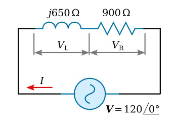
Consider the circuit of figure above. The impedance Z of the circuit is the phasor sum of the inductive reactance and the resistance, since these components are in series:
![]()
Applying Ohm's law,

Converting 900 + j650 to polar form,

Since the circuit of figure above contains inductive reactance, it is to be expected that the current will lag the voltage. However, since the circuit is not pure inductance, the current will not lag by a full 90°. The current phasor was calculated and found to be lagging by 35.8°. The phase relationship between applied voltage V and current I is shown on the complex plane of figure below.
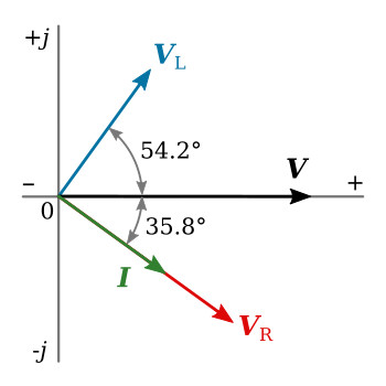
In a series circuit, the sum of the phasors of the voltage drops must equal the applied voltage phasor.
For the series RL circuit,

This is simply the algebraic transformation of the Ohm's-law equation. The value of VR and VL may now be calculated:

Plotting VR and VL on the complex plane of figure above shows that the voltage across the resistance is in phase with the current. The voltage across the inductance leads the current by 90°.
The phasor sum of VR and VL is given by


