Home > Textbooks > Basic Electronics > DC Network Analysis > Thevenin's Theorem >
DC Network Analysis
Thevenin's Theorem
Thevenin's theorem is a method of circuit analysis that involves reducing a complex circuit to a simple equivalent circuit. Thevenin's theorem is frequently used to make circuit analysis simpler.
Thevenin's theorem is especially useful in analyzing circuits where only one particular resistor in the circuit (called the load) is subject to change. Example:
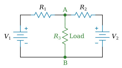
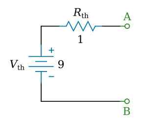
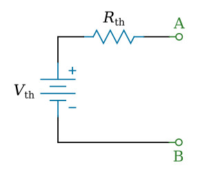
Thevenin's theorem states: Any linear electrical circuit can be replaced at terminals A and B by a simple series circuit consisting of an equivalent voltage source Vth and an equivalent resistance Rth.
Note: A linear circuit is an electronic circuit in which the electronic components' values (such as resistance, conductance, capacitance, inductance, gain, etc.) do not change with the level of voltage or current in the circuit.
The equivalent series circuit will provide the same current through a load as would the original circuit. The equivalent voltage Vth is the voltage "seen" between the two terminals (A and B) being considered in the original network with the load resistance removed. The equivalent resistance Rth is the resistance "seen" between the terminals of the original network when all voltage sources of the original circuit are replaced by a short circuit (wire) and all current sources are replaced by an open circuit (break).
The figure below shows the application of Thevenin's theorem to a simple network. When Thevenin's theorem is applied, the current through RL of the figure below (view A) is the same as the current in RL of the figure below (view D).
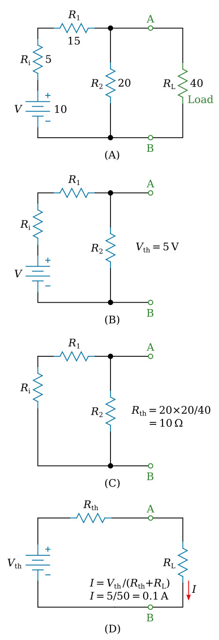
It must be pointed out that Thevenin's theorem establishes equivalency for RL only. The current, voltage, and power of RL in the figure above (view D) are therefore the same as in the figure above (view A). The power supplied to the circuit of figure above (view D) by Vth is not the same as the power supplied to the circuit of figure above (view A) by V.
Thevenin's theorem has the effect of removing a portion of a circuit to make the remaining circuitry easier to analyze. Use of Thevenin's theorem is further demonstrated by the following examples.
Example 1:
Find the Thevenin-equivalent circuit of the circuit shown in the figure below.
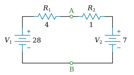
Solution:
Calculating the equivalent voltage Vth
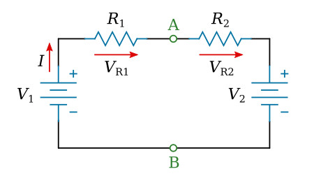
Use Kirchhoff's voltage law and Ohm's law to calculate the current I through elements in series (see the figure above):

The voltage between the points A and B can be figured from the voltages V2 and VR2. This is our equivalent voltage Vth in the equivalent circuit:

Calculating the equivalent resistance Rth
Replace the voltage sources V1 and V2 with a wire:
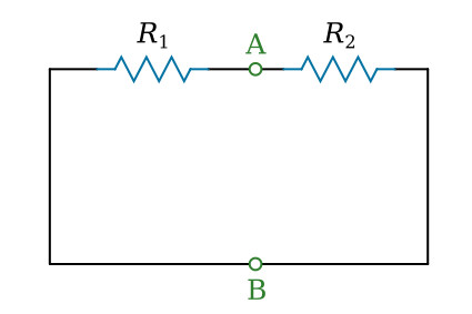
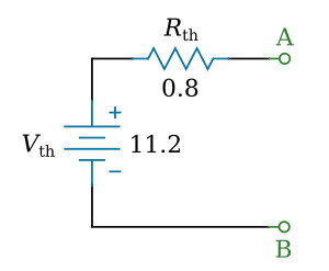
The resistance between the points A and B is equal to R1 and R2 in parallel: 0.8 Ω. This is our equivalent resistance Rth in the equivalent circuit:
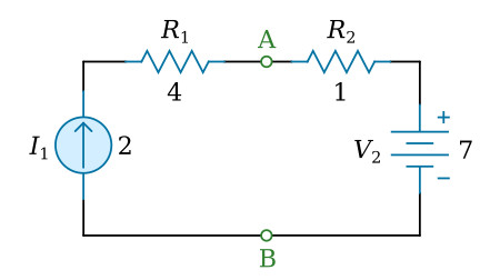
Example 2:
Find the Thevenin-equivalent circuit of the circuit shown in the figure below.
Solution:
Calculating the equivalent voltage Vth
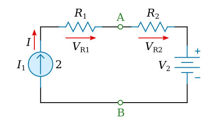
The current I through elements in series is equal to I1.
The voltage between the points A and B can be figured from the voltages V2 and VR2. This is our equivalent voltage Vth in the equivalent circuit:

Calculating the equivalent resistance Rth
Replace the current source I1 with a break and the voltage source V2 with a wire:
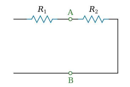
The resistance between the points A and B is equal to R2: 1 Ω. This is our equivalent resistance Rth in the equivalent circuit: