


Home > Textbooks > Basic Electronics > Flip-Flops > D Flip-Flop >
Flip-Flops
D Flip-Flop
The D flip-flop is a two-input flip-flop. The inputs are the data (D) input and a clock (CLK) input. The clock is a timing pulse generated by the equipment to control operations. The D flip-flop is used to store data at a predetermined time and hold it until it is needed. This circuit is sometimes called a delay flip-flop. In other words, the data input is delayed up to one clock pulse before it is seen in the output.
The simplest form of a D flip-flop is shown in the figure below, view A. Now, follow the explanation of the circuit using the truth table and the timing diagram shown in the figure, views B and C.
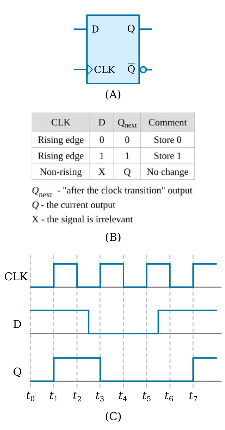
Depending on the circuit design, the clock (CLK) can be a square wave, a constant frequency, or asymmetrical pulses. In this example the clock (CLK) input will be a constant input at a given frequency. This frequency is determined by the control unit of the equipment. The data (D) input will be present when there is a need to store information. Notice in the truth table that output Q reflects the D input only when the clock transitions from 0 to 1 (LOW to HIGH).
Let’s assume that at t0, CLK is 0, D is 1, and Q is 0. Input D remains at 1 for approximately 2 1/2 clock pulses. At t1, when the clock goes to 1, Q also goes to 1 and remains at 1 even though D goes to 0 between t2 and t3. At t3, the positive-going pulse of the clock causes Q to go to 0, reflecting the condition of D. The positive-going clock pulse at t5 causes no change in the output because D is still LOW. Between t5 and t6, D goes HIGH, but Q remains LOW until t7 when the clock goes HIGH.
The key to understanding the output of the D flip-flop is to remember that the data (D) input is seen in the output only after the clock has gone HIGH.
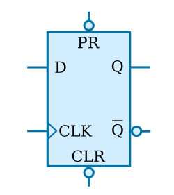
You may see D flip-flop symbols with two additional inputs - CLR (clear) and PR (preset). These inputs are used to set the start condition of the flip-flop - CLR sets Q to 0; PR sets Q to 1. The figure below shows the standard symbol with the CLR and PR inputs. Since these inputs are preceded by inverters (part of the flip-flop), a LOW-going signal is necessary to activate the flip-flop. These signals (CLR and PR) override any existing condition of the output.
You may also see an inverter at the clock input. In this case, the output will change on the negative-going transition of the clock pulse.


