


Home > Textbooks > Basic Electronics > Flip-Flops > T Flip-Flop >
Flip-Flops
T Flip-Flop
The toggle, or T, flip-flop is a two-input flip-flop. The inputs are the toggle (T) input and a clock (CLK) input. If the toggle input is HIGH, the T flip-flop changes state (toggles) when the clock signal is applied. If the toggle input is LOW, the T flip-flop holds the previous state.
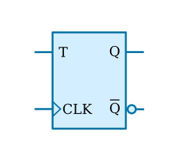
The standard symbol for a T flip-flop is illustrated in the figure above. The clock input may be preceded by an inverter. An inverter indicates a flip-flop will toggle on a HIGH-to-LOW transition of the clock pulse. The absence of an inverter indicates the flip-flop will toggle on a LOW-to-HIGH transition of the pulse.
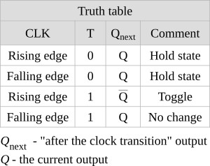
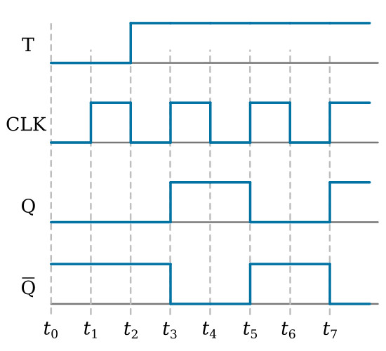
Now, follow the explanation of the circuit using the truth table and the timing diagram shown in the figure above. The timing diagram shows the inputs and the resulting outputs. We will assume an initial condition (t0) of Q being LOW and Q being HIGH. At t1, when the clock changes from a LOW to a HIGH, the outputs remain the same as the T input is LOW. The T input goes HIGH at t2. At t3, the clock changes from a LOW to a HIGH and the device changes state; Q goes HIGH and Q goes LOW. The outputs remain the same at t4 since the device is switched only by a LOW-to-HIGH transition. At t5, when the clock goes HIGH, Q goes LOW and Q goes HIGH; they remain that way until t7.
Between t3 and t7, two complete cycles of CLK occur. During the same time period, only one cycle is observed for Q or Q. Since the output frequency is one-half the clock (input) frequency, this device can be used to divide the input frequency by 2.
The most commonly used T flip-flops are J-K flip-flops wired to perform a toggle function. This use will be demonstrated later in this section.


