Home > Textbooks > Basic Electronics > Flip-Flops > R-S Flip-Flop >
Flip-Flops
R-S Flip-Flop
The R-S flip-flop is used to temporarily hold or store information until it is needed. A single R-S flip-flop will store one binary digit, either a 1 or a 0. Storing a four-digit binary number would require four R-S flip-flops.
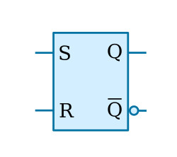
The standard symbol for the R-S flip-flop is shown in the figure below. The name is derived from the inputs, R for reset and S for set. It is often referred to as an SR latch. The outputs Q and Q (¬Q) are complements, as mentioned earlier.
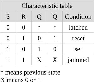
The R-S flip-flop has two output conditions. When the Q output is HIGH and Q is LOW, the flip-flop is set. When Q is LOW and Q is HIGH, the flip-flop is reset. When the R and S inputs are both HIGH, the states of Q and Q outputs usually depend on the type of the R-S flip-flop. When this condition exists, the flip-flop is considered to be jammed and the outputs cannot be used. The jammed condition is corrected when either S or R goes LOW.
To set the flip-flop requires a HIGH on the S input and a LOW on the R input. To reset, the opposite is required; S input LOW and R input HIGH. When both R and S are LOW, the flip-flop will hold or "latch" the condition that existed before both inputs went LOW.
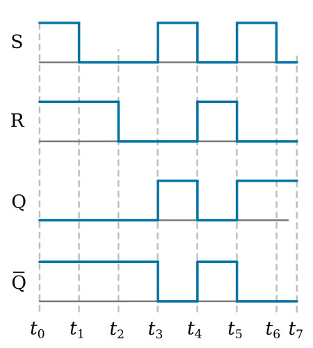
In our description of R-S flip-flop operation, let’s assume that two signals are applied to the S and R inputs and the AND-OR type of R-S flip-flop is used. Refer to the figure below. At time t0, both S and R are HIGH, as a result, Q is LOW and Q is HIGH. This is the jammed state and as mentioned earlier, cannot be used in logic circuitry. At t1, S goes LOW and R remains HIGH; Q remains LOW and Q remains HIGH; the flip-flop is reset. At t2 R goes LOW and S remains LOW; the flip-flop is latched in the reset condition. At t3, S goes HIGH and R remains LOW; the flip-flop sets. At t4 S goes LOW and R goes HIGH; the flip-flop resets. When S and R input conditions reverse at t5, the flip-flop sets. The circuit is put in the latch condition at t6 when S goes LOW.