


Home > Textbooks > Basic Electronics > Flip-Flops > J-K Flip-Flop >
Flip-Flops
J-K Flip-Flop
The J-K flip-flop is the most widely used flip-flop because of its versatility. When properly used it may perform the function of an R-S, T, or D flip-flop. The standard symbol for the J-K flip-flop is shown in view A of the figure below.
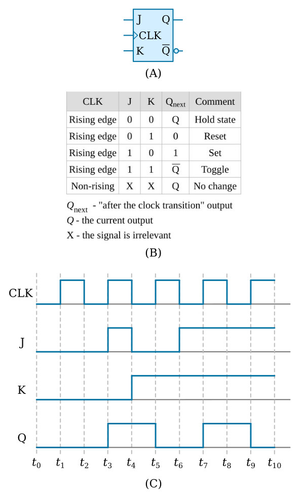
The J-K is a three-input device. The J and K inputs are for data. The CLK input is for the clock. The outputs Q and Q are the normal complementary outputs.
Observe the truth table and timing diagram in the figure above, views B and C, as the circuit is explained.
The first line of the truth table shows a positive-going CLK, and J and K at 0, or LOW. This corresponds to t1 on the timing diagram. In this condition the flip-flop holds the previous condition of the output. In this case the flip-flop is reset. If the circuit were set when these inputs occurred, it would remain set.
At time t3, we have a positive-going clock pulse and a HIGH on the J input. This causes the circuit to set, Q to go HIGH, and Q to go LOW.
At t4, J goes LOW, K goes HIGH, and the clock is in a negative-going transition. There is no change in the output because all actions take place on the positive clock transition.
At t5, when J is LOW, K is HIGH; the clock is going positive, the flip-flop resets, Q goes LOW, and Q goes HIGH.
With both J and K HIGH and a positive-going clock (as at t7), the flip-flop will toggle or change state with each clock pulse. It will continue to toggle as long as J and K both remain HIGH.
The last line of the truth table indicates that as long as the clock is in any condition other than a positive-going transition, there will be no change in the output regardless of the state of J or K.
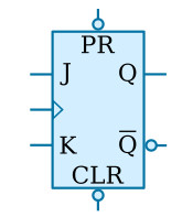
You may see J-K flip-flop symbols with two additional inputs - CLR (clear) and PR (preset). These inputs are used to set the start condition of the flip-flop - CLR sets Q to 0; PR sets Q to 1. The figure below shows the standard symbol with the CLR and PR inputs. Since these inputs are preceded by inverters (part of the flip-flop), a LOW-going signal is necessary to activate the flip-flop. These signals (CLR and PR) override any existing condition of the output.
As mentioned at the beginning of this section, J-K flip-flops may be used as R-S, T, or D flip-flops.
The figure below shows how a J-K can be made to perform the other functions.
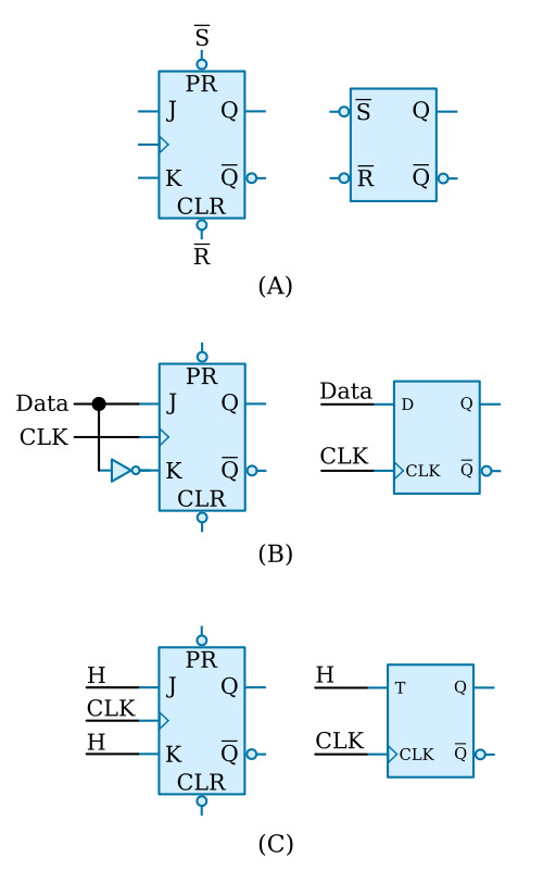
In view A, using just the PS and CLR inputs of the J-K will cause it to react like an R-S flip-flop.
In view B, data is applied to the J input. This same data is applied to the K input through an inverter to ensure that the K input is in the opposite state. In this configuration, the J-K performs the same function as a D flip-flop.
View C shows both the J and K inputs held at 1, or HIGH. The flip-flop will change state or toggle with each positive-going transition of the clock just as a T flip-flop will.


