


Home > Textbooks > Basic Electronics > Oscillators > Armstrong Oscillator >
Oscillators
Armstrong Oscillator
The Armstrong oscillator (also known as the Meissner oscillator) is used to produce a sine-wave output of constant amplitude and fairly constant frequency. The circuit is generally used as a local oscillator in receivers, as a signal source in signal generators, and as a variable frequency oscillator over the medium and high frequency ranges.
The Armstrong oscillator uses an LC parallel-tuned circuit to establish the frequency of oscillation, with feedback being provided by a separate tickler coil of proper polarity to sustain oscillation. It operates Class C with stabilized bias for applications where waveform is not important, and Class A where waveform is important.
The LC circuit (commonly called a tank circuit) determines the frequency of oscillation. The tank circuit can be located in either the base or the collector circuits to produce two versions of this circuit known as the tuned-base and tuned-collector circuits, respectively. Although the three basic transistor configurations can be used, generally, only two, the common-emitter and common-base, are used in practice. The use of the common-emitter configuration is preferred to the others, as it has input and output impedances that are more easily matched. As the input and output are 180° out of phase in the common emitter circuit it is necessary to provide a 180° phase shift to bring the output in-phase so that oscillation may be sustained. In the common base and common-collector arrangements, the input and output are already in-phase therefore, no phase shift is required. The basic advantage of the Armstrong oscillator, however, is that since the feedback is developed by a separate (tickler) coil, the amount and polarity of the feedback are easily adjusted at the time of manufacture by changing the number of turns or direction of the winding.
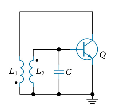
The basic configuration of the Armstrong oscillator circuit is shown in the figure above. This is a common-emitter configuration which provides the 180-degree phase shift between the base and collector. The tank circuit is composed of inductor L2 and capacitor C. It is located in the base circuit. The feedback network uses L1 (the collector load) as the primary and L2 as the secondary winding of a coupling transformer to provide a 180-degree phase shift. Bias arrangements and capacitor couplings are omitted for the sake of simplicity.
The circuit operation of the oscillator is as follows: As the oscillator is switched on, current flows through the transistor as determined by the biasing circuit. The bias circuit causes collector current to flow through L1. This current through L1 develops a magnetic field which induces a voltage into L2 through the mutual induction between L1 and L2. At this time, resonant tank capacitor charges to this voltage; the tank circuit now has stored energy. With an increasing signal on its base, Q conducts harder. With Q conducting harder, a larger voltage is induced into L2, and a larger signal is coupled back to the base of Q. The transistor will continue to increase in conduction until it reaches saturation. At saturation, the collector current of Q is at a maximum value and cannot increase any further. At this time C begins to act as a voltage source and discharges. As the voltage across C decreases, its energy is transferred to the magnetic field of L2. The collector current decreases, which is caused by the decreasing potential at the base of Q. A decrease in collector current induces a decreasing voltage into L2 and makes the base of Q more negative. This is regenerative action; it continues until Q is driven into cutoff. When Q is cut off, the tank circuit continues to flywheel, or oscillate. The flywheel effect not only produces a sine-wave signal, but it aids in keeping Q cut off. Without feedback, the oscillations of L2 and C would dampen out after several cycles.
Tuned-base oscillator
The full version of the tuned-base oscillator using the common-emitter configuration is shown in the figure below. One voltage supply is used, with fixed bias being supplied by voltage-dividing resistors R1 and RB. Emitter swamping resistor RE bypassed by C1, is used for temperature stabilization.
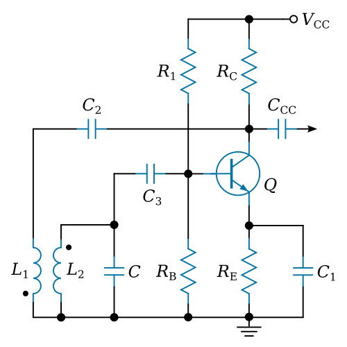
The collector is shunt-fed through RC, with C2 serving as the coupling (and blocking) capacitor for the tickler coil L1, to prevent shunting the DC collector voltage to ground. The tuned tank consists of L2 and tuning capacitor C, coupled to the base of transistor by capacitor C3, which prevents short-circuiting the base bias to ground through the tank inductor.
When the circuit is energized, the initial bias is determined by R1 and RB, and oscillation is built up by feedback from L1 to L2. Besides acting as a thermal stabilizer and swamping resistor, the combination of RE and C1 builds up a degenerative bias which places operation in the Class C region. That is, while RB and R1 produce a forward bias, RE produces a reverse bias, with the algebraic sum of the two biases providing the operating bias. Circuit constants can be adjusted changing the values of parts to produce practically any value of bias between Class A and C. The output signal is taken from the collector through CCC. The output frequency is determined by the resonant frequency of the tank.
Tuned-collector oscillator
The tuned-collector oscillator using the common-emitter configuration is shown in the figure below. One voltage supply is used, with fixed base bias being supplied by voltage dividing resistors R1 and RB as in the tuned base oscillator shown previously. The arrangement below uses series base feed, together with series collector feed through the tank inductor, although parallel feed may be used.
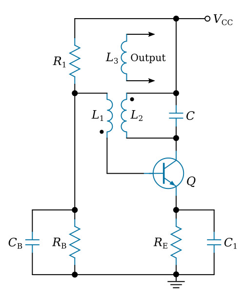
Base bias resistor RB is shunted by CB, to prevent signal variations from affecting the fixed base bias. Emitter swamping and base-biasing arrangements operate exactly the same as in the tuned-base oscillator. The output signal, however, is taken through inductive coupling to the tank circuit. Use of series collector and base bias feeds eliminates the need for coupling and blocking capacitors.
The feedback polarity is arranged to provide a 180-degree phase shift, in order to produce positive feedback similar to that obtained in the tuned-base oscillator. Placing the tank in the collector circuit provides an effective swamping capacitance across the collector and emitter, to minimize effects due to the variations of collector-emitter capacitance.


