


Home > Textbooks > Basic Electronics > Oscillators > Crystal Oscillators >
Oscillators
Crystal Oscillators
Crystal oscillators are those in which a specially-cut crystal controls the frequency. Crystals are thin sheets, or wafers, cut from a piezoelectric material and ground to a specific thickness to obtain the desired resonant frequency. Crystals exhibit a characteristic known as the piezoelectric effect. The piezoelectric effect is the property of a crystal by which mechanical forces produce electrical charges and, conversely, electrical charges produce mechanical forces. This effect is a form of oscillation similar to the flywheel effect of a tank circuit.
The crystals are mounted in holders, which support them physically and provide electrodes by which voltage is applied. The holder must allow the crystals freedom for vibration. A crystal oscillator is usually used to produce an output which is highly stable and at a very precise frequency. The crystal may be used with a tank circuit, or it may perform alone.
The piezoelectric effect can be seen in a number of crystal substances. Among these are quartz, Rochelle salt, and tourmaline. Although quartz does not exhibit the piezoelectric effect to the degree that Rochelle salt does, quartz is used for frequency control in oscillators because of its greater mechanical strength. Tourmaline is physically strong like quartz; but because it is more expensive, it is not used extensively as a frequency determining device. This discussion will deal only with the quartz crystal.
The Q factor of a crystal is many times greater than that of an LC tank circuit. The high Q is present because the resistance in the crystal is small. Commercially produced crystals typically range in Q from 104 to 106. The high Q causes the frequency stability to be much greater than that of an ordinary LC tank circuit. This is the reason a crystal is used in many sine-wave generator circuits.
The amount of current that can safely pass through a crystal ranges is restricted. When the rated current is exceeded, the amplitude of mechanical vibration becomes too great, and the crystal may crack. Overloading the crystal affects the frequency of vibration because the power dissipation and crystal temperature increase with the amount of load current.
Crystals as Tuned Circuits
The frequency for which a crystal is ground is referred to as the natural resonant frequency of the crystal. Voltage applied to the crystal produces mechanical vibrations which, in turn, produce an output voltage at the natural resonant frequency of the crystal. A vibrating crystal can be represented by an equivalent electrical circuit composed of capacitance, inductance, and resistance.
The figure below, view (A), illustrates the symbol of a crystal; view (B) shows an equivalent circuit for the crystal. Capacitor CS, inductor LS, and resistor RS in view (B) represent the electrical equivalent of the quartz crystal. CP represents the capacitance between the metal plates of the crystal holder.
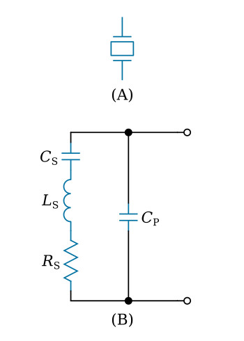
The capacitance of the holder, CP, is about 100 times as great as the vibration capacitance, CS, of the crystal itself. The presence of both series and parallel resonant frequencies is revealed by the impedance versus frequency characteristics of a typical quartz crystal shown in the figure below. This curve is very sharp, indicating a high Q. It is found in practice that the L/C ratio of the equivalent circuit is extremely large compared with that of a conventional tank circuit. For most crystals, the difference in frequency between fP and fS is very small compared to the series resonant frequency of the crystal.
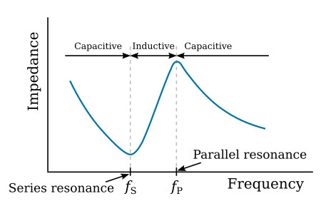
Depending upon the circuit characteristics, the crystal can act as a capacitor, an inductor, a series resonant circuit, or a parallel resonant circuit. At series resonance (fS) of capacitance CS and inductance LS, the crystal has a minimum impedance and the resonance frequency of the oscillator circuit is determined only by the mechanical vibrating characteristics of the crystal. Above resonance the series resonant circuit acts inductively, and below resonance it acts capacitively.
The series resonant frequency of the crystal is given as

Above the frequency of series resonance (fS), the inductive reactance of inductance LS is greater than the capacitive reactance of capacitance CS. The combination (LS and CS) then appears as a net inductance. This net inductance forms a parallel resonant circuit with capacitance CP and any circuit capacitance appearing across the crystal. A parallel resonant circuit has a maximum impedance at the parallel-resonant frequency. Below resonance the parallel resonant circuit acts inductively, and above resonance it acts capacitively.
The parallel resonant frequency of the crystal is given as

Crystal-Controlled Armstrong Oscillator
The crystal-controlled Armstrong oscillator (see the figure below) uses the series-resonant mode of operation of the crystal and functions similarly to the basic tuned-collector Armstrong oscillator. Increased frequency stability is obtained with the insertion of a crystal in the feedback path. However, the frequency is essentially fixed by the crystal. To obtain a variable frequency oscillator, different crystals may be inserted in the circuit. Variable capacitor C1 makes the circuit tunable to the selected crystal frequency.
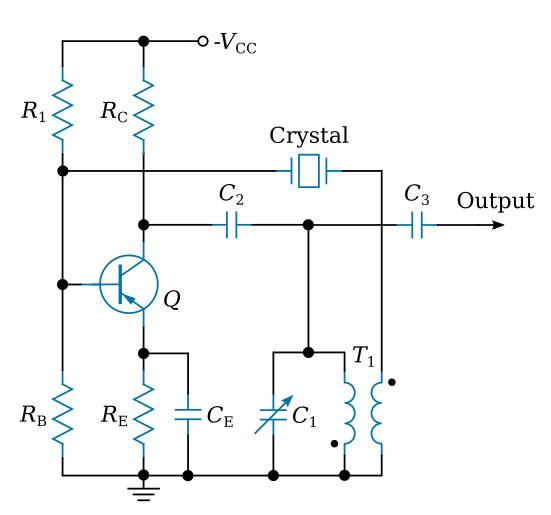
Regenerative feedback from the collector to base is through the mutual inductance between the transformer windings of T1. This provides the necessary 180-degree phase shift for the feedback signal. Resistors RB, R1, and RC provide the base and collector bias voltage. Capacitor CE bypasses AC variations around emitter resistor RE. At frequencies above and below the series-resonant frequency of the selected crystal, the impedance of the crystal increases and reduces the amount of feedback signal. This, in turn, prevents oscillations at frequencies other than the series-resonant frequency.
Colpitts-Type Crystal Oscillator
This oscillator uses a crystal unit as a parallel-resonant circuit. It is a modified Colpitts oscillator, which was described previously. They operate in the same way except that the crystal unit replaces the inductor of the basic Colpitts oscillator.
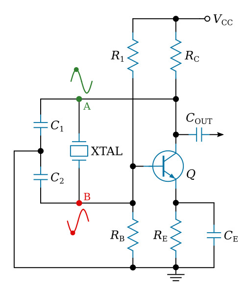
The figure above shows the common-emitter configuration of the Colpitts oscillator with the feedback supplied from collector to base. The resistors in the circuit provide the proper bias and stabilization conditions. The crystal unit and capacitors C1 and C2 determine the output frequency of the oscillator. Capacitors C1 and C2 form the voltage divider for this circuit. The signal developed at point A is 180 degrees out of phase with the signal at point B. Therefore, the signal at point B can be coupled back to the base of Q as a regenerative feedback signal to sustain oscillations.


