


Home > Textbooks > Basic Electronics > Oscillators > Colpitts Oscillator >
Oscillators
Colpitts Oscillator
The Colpitts oscillator is very similar to the Hartley oscillator, except that two capacitors are used in the tank circuit instead of a tapped coil. The Hartley oscillator has a tap between two coils, while the Colpitts has a tap between two capacitors. You can change the frequency of the Colpitts either by varying the inductance of the coil or by varying the capacitance of the two capacitors in the tank circuit. Transistor operation is class C where waveform is not important and class A where waveform is important.
The LC (tank) circuit determines the frequency of oscillation. The tank circuit consists of two series-connected capacitors in parallel with the inductor. The two series capacitors will act as a capacitance voltage divider across the inductor (in addition to tuning the coil to resonance). The capacitance feedback voltage divider may be connected so as to provide an inphase voltage or an out-of-phase voltage, to suit the various transistor configurations used. The reactance ratio of the two series capacitors is usually chosen to match the input-output resistances of the transistor used.
The basic common-emitter configuration of the Colpitts transistor oscillator is shown in the figure below. For simplicity, bias arrangements are not shown, but are discussed later. It is assumed that forward bias is initially applied to the emitter-base junction and that reverse bias is applied to the collector-base junction. Since, in the common-emitter circuit, the base and collector elements are out of phase, it is necessary to provide a 180° phase shift to obtain the positive (regenerative) feedback needed to sustain oscillation. This phase shift is achieved by grounding the common capacitor connection, to make the polarity of the voltage across C1 opposite to the voltage across C2 (in respect to ground). The frequency stability is better than that of the Hartley oscillator and the Armstrong oscillator, because the tank capacitors effectively swamp out any slight changes of parasitic capacitances that exist between the emitter and collector and between the emitter and base of the transistor.
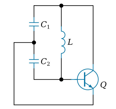
The Colpitts circuit oscillates at

where Ct is the capacitance of C1 and C2 connected in series:

The shunt-fed Colpitts oscillator arranged in common-emitter transistor configuration is shown schematically in the figure below. One voltage supply is used, with fixed bias supplied by voltage-dividing resistors R1 and RB. Emitter-swamping resistor RE, bypassed by C5, is used for temperature stabilization. The tank circuit is shunt-fed through capacitor C3.
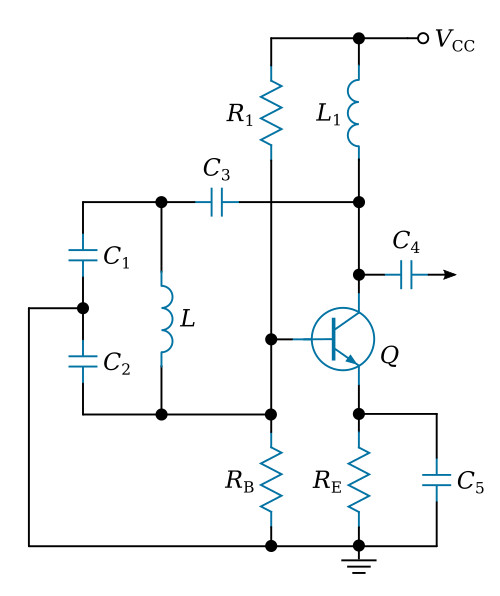
When the circuit is energized, the initial bias is determined by R1 and RB and oscillation is built up by feedback from the tank circuit through divider capacitor C2. Since the divider is grounded at the common connection, opposite polarities exist across capacitors C1 and C2 in respect to ground, with the voltage across these capacitors determined by the capacitive reactance ratio. Thus, a voltage that is out of phase with the collector is applied between the base and emitter to supply a positive feedback and sustain oscillation.
The combination of RE and C5 provides an emitter-swamping resistor for the thermal stabilization, with sufficient capacitance as a bypass to permit degenerative voltage buildup to occur and bias to the transistor into the class B or C operating region after a few initial oscillations. The values of R1 and RB are usually chosen to provide class A bias for easy starting. The amplitude of oscillation is essentially regulated by driving the transistor to saturation on one portion of the cycle and to cutoff on the other portion. Although such action normally would cause abrupt changes and distort the waveform, the tank circuit effectively smooths out the pulsations in class C operation to provide oscillations that are essentially sine waves.
The oscillator output may be taken from a capacitor connected to the collector or from an inductor coupled to the tank inductor.


