


Home > Textbooks > Basic Electronics > Oscillators > LC Oscillators >
Oscillators
LC Oscillators
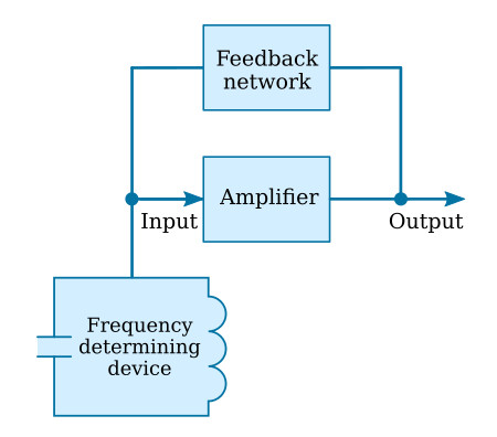
The figure below shows a block diagram of a typical LC oscillator. Notice that the oscillator contains three main sections: a frequency-determining device, an amplifier, and a feedback circuit. The frequency-determining device in an LC oscillator is usually an LC tank circuit. Although the tank circuit is normally found in the input circuit of an oscillator, it sometimes appears in the output circuit. The amplifier amplifies and automatically deliver to the input circuit the proper amount of energy to sustain oscillations. The feedback circuit couples energy of the proper amount and of the correct phase from the output to the input circuit to sustain oscillations.
When a tank circuit is used to develop oscillations in an oscillator, the output frequency of the oscillator is primarily the resonant frequency of the tank circuit and can be found by the formula

Feedback
Feedback is the process of transferring energy from a high-level point in a system to a low-level point in a system. This means transferring energy from the output of an amplifier back to its input. If the output feedback signal opposes the input signal, the feedback is degenerative (negative). However, if the feedback aids the input signal, the feedback is regenerative (positive). Regenerative or positive feedback is one of the requirements to sustain oscillations in an oscillator. This feedback can be applied in any of several ways to produce a practical oscillator circuit.
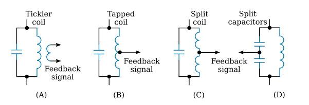
The feedback signal is coupled from the tank circuit by either of two means. The first method is to take some of the energy from the inductor. This can be done by any one of the three ways shown in the figure below, views (A), (B), and (C). When an oscillator uses a tickler coil, as shown in view (A), it is referred to as an Armstrong oscillator. When an oscillator uses a tapped coil (view (B)) or a split coil (view (C)), it is referred to as a Hartley oscillator. The second method of coupling the feedback signal is to use two capacitors in the tank circuit and tap the feedback signal between them. This is shown in view (D). An oscillator using this method is referred to as a Colpitts oscillator. Each of these particular oscillators is named after the person who originally designed them.
Configuration of Oscillators
Any of the three basic amplifier configurations (common collector, common base, or common emitter) may be used for the oscillator circuit. However, certain considerations in the application of the circuit, such as the operating frequency and output power required, usually determine which of the three configurations is to be used.
Common-Collector Configuration
Since there is no phase reversal between the input and output circuits of a common-collector configuration, the feedback network does not need to provide a phase shift. However, since the voltage gain is less than unity and the power gain is low, the common-collector configuration is very seldom used in oscillator circuits.
Common-Base Configuration
The power gain and voltage gain of the common-base configuration are high enough to give satisfactory operation in an oscillator circuit. The wide range between the input resistance and the output resistance make impedance matching slightly harder to achieve in the common-base circuit than in the common-emitter circuit. An advantage of the common-base configuration is that it exhibits better high-frequency response than does the common-emitter configuration. Since there is no phase reversal between the input and output circuits of a common-base configuration, the feedback network does not need to provide a phase shift.
Common-Emitter Configuration
The common-emitter configuration has high power gain and is used in low-frequency applications. For the energy which is fed back from the output to be in phase with the energy at the input, the feedback network of a common-emitter oscillator must provide a phase shift of approximately 180 degrees. An advantage of the common-emitter configuration is that the medium resistance range of the input and output simplifies the job of impedance matching.


