Home > Textbooks > Basic Electronics > Waveform Generators > Astable Multivibrator >
Waveform Generators
Astable Multivibrator
An astable multivibrator is also known as a free-running multivibrator. It is called free-running because it alternates between two different output voltage levels during the time it is on. The output remains at each voltage level for a definite period of time. If you looked at this output on an oscilloscope, you would see continuous square or rectangular waveforms. The astable multivibrator has two outputs, but no inputs.
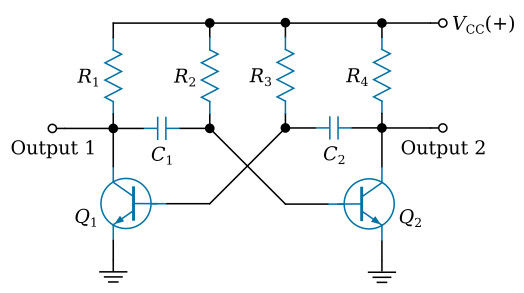
An astable multivibrator, as shown in the figure above, is basically two amplifier circuits arranged with regenerative feedback. One of the amplifiers is conducting while the other is cut off. The astable multivibrator is said to oscillate. To understand why the astable multivibrator oscillates, assume that transistor Q1 saturates and transistor Q2 cuts off when the circuit is energized. This situation is shown in the figure below. We assume Q1 saturates and Q2 is in cutoff because the circuit is symmetrical; that is, R1 = R4, R2 = R3, C1 = C2, and Q1 = Q2. It is impossible to tell which transistor will actually conduct when the circuit is energized. For this reason, either of the transistors may be assumed to conduct for circuit analysis purposes.
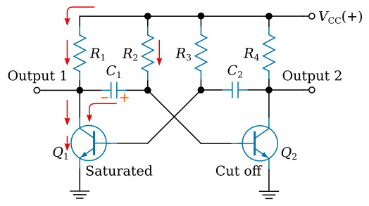
Essentially, all the current in the circuit flows through Q1; Q1 offers almost no resistance to current flow. Notice that capacitor C1 is charging. Since Q1 offers almost no resistance in its saturated state, the rate of charge of C1 depends only on the time constant of R2 and C1 (recall that τ = RC). Notice that the right-hand side of capacitor C1 is connected to the base of transistor Q2, which is now at cutoff.
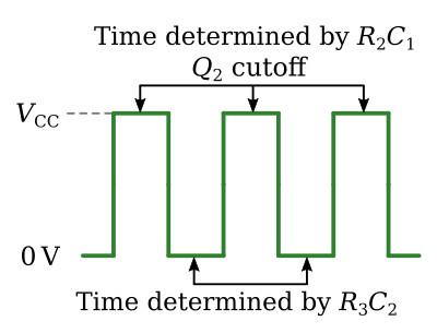
Let's analyze what is happening. The right-hand side of capacitor C1 is becoming increasingly positive. If the base of Q2 becomes sufficiently positive, Q2 will conduct. After a certain period of time, the base of Q2 will become sufficiently positive to cause Q2 to change states from cutoff to conduction. The time necessary for Q2 to become saturated is determined by the time constant R2C1.
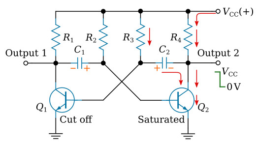
The next state is shown in the figure below. The positive voltage accumulated on the right side on capacitor C1 has caused Q2 to conduct. Now the following sequence of events takes place almost instantaneously. Q2 starts conducting and quickly saturates, and the voltage at output 2 changes from approximately VCC to approximately 0 volts. This change in voltage is coupled through C2 to the base of Q1, forcing Q1 to cutoff. Now Q1 is in cutoff and Q2 is in saturation. Notice that the figure below is the mirror image of the figure above. In the figure below the left side of capacitor C2 becomes more positive at a rate determined by the time constant R3C2. As the left side of C2 becomes more positive, the base of Q1 also becomes more positive. When the base of Q1 becomes positive enough to allow Q1 to conduct, Q1 will again go into saturation. The resulting change in voltage at output 1 will cause Q2 to return to the cutoff state.
Look at the output waveform from transistor Q2, as shown in the figure below. The output voltage (from either output of the multivibrator) alternates from approximately 0 volts to approximately VCC, remaining in each state for a definite period of time. In some applications, the time period of higher voltage (VCC) and the time period of lower voltage (0 volts) will be equal. Other applications require differing higher- and lower-voltage times.