


Home > Textbooks > Basic Electronics > Waveform Generators > Op-Amp Astable Multivibrator >
Waveform Generators
Op-Amp Astable Multivibrator
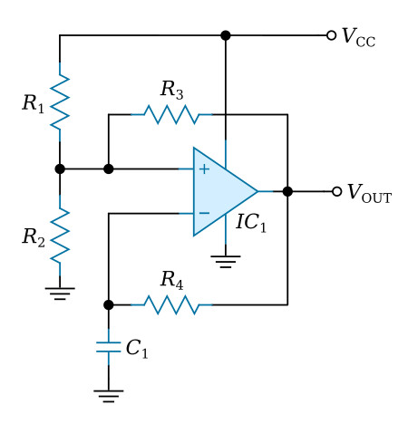
This multivibrator provides a square-wave signal with an output voltage swing of approximately 0 to VCC. The multivibrator circuitry consists of an op-amp, IC1, and the associated components shown in the figure above. Since a single power supply (VCC) is used for the op-amp, equal value resistors, R1 and R2, are used to provide a bias voltage at the positive input of the op-amp equal to one-half of the supply voltage.
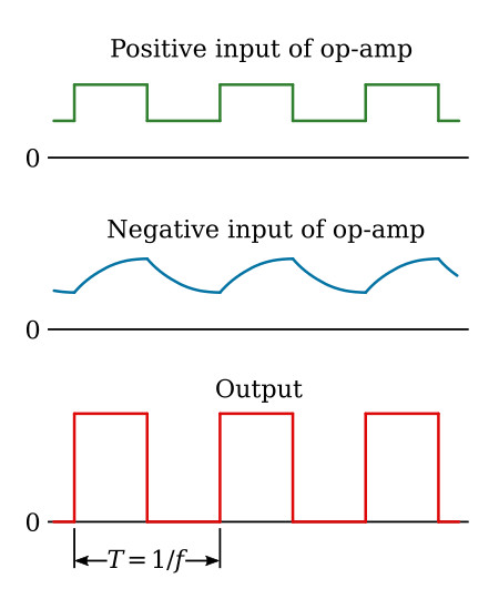
The multivibrator circuitry waveforms are presented in the figure above. Resistor R3 provides positive feedback and, in conjunction with resistors R1 and R2, determines the swing of the square-wave voltage about the bias point at the positive input of the op-amp. When R1, R2, and R3 are equal, the swing of the voltage at the positive input is from VCC/3 to VCC*2/3. The charging and discharging of the R-C network, R4 and C1, produces an almost triangular waveform at the negative input of the op-amp. A change of state of the op-amp output occurs when the negative input voltage level crosses the voltage at the positive input of the op-amp. Thus, the op-amp functions as a comparator, operating in a saturated switching mode, at a frequency f determined by the R4C1 time constant. When R1, R2, and R3 are equal, the frequency can be calculated as


