


Home > Textbooks > Basic Electronics > Waveform Generators > Bistable Multivibrator >
Waveform Generators
Bistable Multivibrator
As the name implies, the bistable multivibrator has two stable states. If a trigger of the correct polarity and amplitude is applied to the circuit, it will change states and remain there until triggered again.
The bistable multivibrator circuit and the associated waveforms are shown in the figure below, views A and B, respectively. In this circuit, R1 and R6 are the collector load resistors. Voltage dividers R1, R2, and R4 provide forward bias for Q2; R6, R5, and R3 provide forward bias for Q1. These resistors also couple the collector signal from one transistor to the base of the other. Observe that this is direct coupling of feedback. This type of coupling is required because the circuit depends on input triggers for operation, not on RC time constants inside the circuit. C1 and C2 couple the input triggers to the transistor bases. Capacitors C3 and C4 transmit almost instantaneously any changes in voltage from the collector of one transistor to the base of the other.
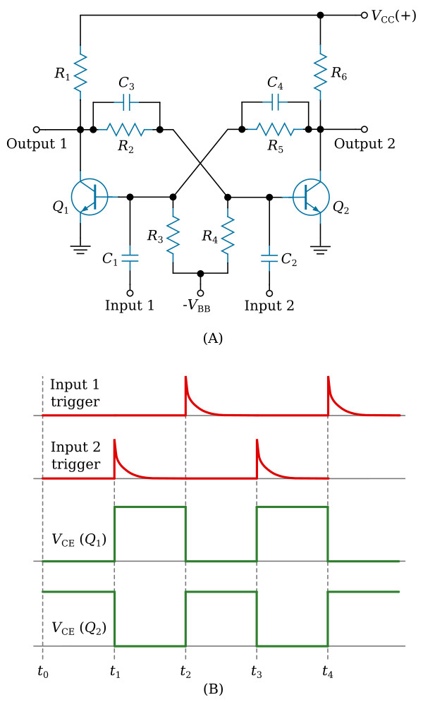
Notice that the circuit is symmetrical; that is, each transistor amplifier has the same component values. When power is first applied, due to some slight difference between the two circuits, one transistor will be cut off and the other transistor will be saturated. Assume that Q1 is initially saturated and Q2 is cut off. The circuit is in a stable state and will remain there until a trigger is applied to change the state.
At t1, a positive trigger is applied to the base of Q2 through C2. The trigger overcomes cutoff bias on Q2 and causes it to conduct. As Q2 goes into conduction, its collector voltage becomes approximately 0 V. The negative-going change at the Q2 collector causes a reverse bias on the base of Q1. As the conduction of Q1 decreases to the cutoff point, the collector voltage becomes positive. This switching action causes a very rapid change of state with Q2 now conducting and Q1 cut off.
At t2, a positive trigger is applied to the base of Q1 through C1. This time, Q1 is brought into conduction and the regenerative switching action cuts off Q2. The bistable multivibrator will continue to change states as long as triggers are applied.
The bistable multivibrator that most technicians know is commonly known by other names: the Eccles-Jordan circuit and, more commonly, the flip-flop circuit. The flip-flop is a bistable multivibrator, "bi" meaning two; that is, the flip-flop has two stable states. The flip-flop (f/f) can rapidly flip from one state to the other and then flop back to its original state. If a voltmeter were connected to the output of a flip-flop, it would measure either a small positive or negative voltage, or a particularly low voltage (essentially 0 volts). No matter which voltage is measured, the flip-flop would be stable. Remember, stable means that the flip-flop will remain in a particular state indefinitely. It will not change states unless the proper type of trigger pulse is applied.


