


Home > Textbooks > Basic Electronics > Waveform Generators > Monostable Multivibrator >
Waveform Generators
Monostable Multivibrator
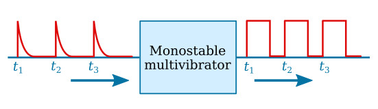
The monostable multivibrator (sometimes called a one-shot multivibrator) is a square- or rectangular-wave generator with just one stable state. The operation of the monostable multivibrator is relatively simple. The input is triggered with a pulse of voltage. The output changes from one voltage level (stable state) to a different voltage level (unstable state). The output remains at this new voltage level for a definite period of time. Then the circuit automatically reverts to its stable state and remains that way until another trigger pulse is applied to the input. The monostable multivibrator actually takes this series of input triggers and converts them to uniform pulses, as shown in the figure below. All of the output pulses are of the same amplitude and time duration.
A standard transistor monostable multivibrator is shown in the figure below. When the circuit is energized, current through small resistor R1 and uncharged capacitor C1 causes Q2 to saturate. Q2 has practically no voltage drop across it, so its collector is essentially at 0 volts. This voltage is coupled through R3 to the base of Q1. Therefore, Q1 is cut off. C1 is charged to nearly VCC through the output circuit (resistor R1) of Q1. The circuit is in its stable state.
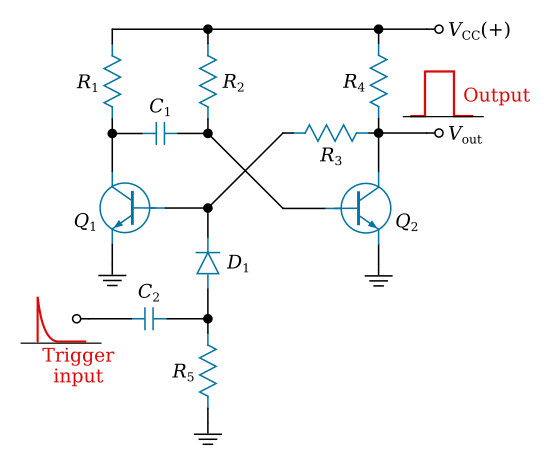
Assume that a positive pulse is applied at the input terminal. C2 and D1 couples this voltage change to the base of Q1 and starts Q1 conducting. Q1 quickly saturates, and its collector voltage drops to ground potential. This sharp voltage decrease is coupled through C1 to the base of Q2, causing Q2 to cut off. The collector voltage of Q2 quickly rises to VCC. This rise in voltage at the collector of Q2 is coupled through R3 to the base of Q1 to keep it conducting.
The monostable multivibrator has now been turned on by applying a pulse at the input. It will turn itself off after a period of time. To see how it does this, look at the figure above again. Q1 is held in saturation by the positive voltage applied through R3 to its base, so the circuit cannot be turned off here. Notice that the base of Q2 is connected to C1. The charge on C1 acts like a battery with its positive terminal on the collector of Q1, and its negative terminal connected to the base of Q2. This voltage across C1 keeps Q2 cutoff. Now, C1 starts to charge to reverse voltage through R2 and Q1. When the voltage at the base of Q2 is such that it is slightly forward biased, collector current will start to flow. The resulting drop in voltage at the collector of Q2 is coupled to Q1 by R3 which causes Q1 to turn off.
74121 Monostable Multivibrator
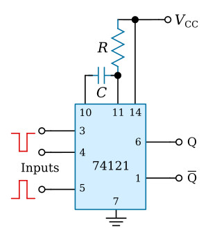
This integrated circuit can generate pulses with a width from about 30 ns to 28 s. The pulse width may be varied by external timing components (R, C) and is approximately defined by the relationship t = 0.7RC. The IC can be triggered by positive or negative input edges.


