Home > Textbooks > Basic Electronics > Waveform Generators > Ramp Generators >
Waveform Generators
Ramp (Sawtooth) Generators
Ramp generators are used to produce a sawtooth waveform. Ideally, the sawtooth waveform consists of a voltage which increases linearly with time until it reaches a predetermined final value, instantaneously returns to zero, and immediately increases again as the cycle repeats. One application of this waveform is to produce a linear time base for use in analog oscilloscopes. Since, in this application, the sawtooth waveform causes an electron beam to sweep across the oscilloscope screen it is also called a sweep voltage. All linear voltage sweep circuits basically operate in a similar manner. A capacitor is allowed to charge through a high resistance until a predetermined voltage is reached. At that point a low resistance discharge path is provided and the capacitor is rapidly discharged. At some point in the capacitor discharge time, the discharge path is opened and the cycle is repeated. Variations in sweep circuits are produced by varying the values of the elements controlling the time of charge and discharge. Sometimes a constant current source is used to charge the capacitor.
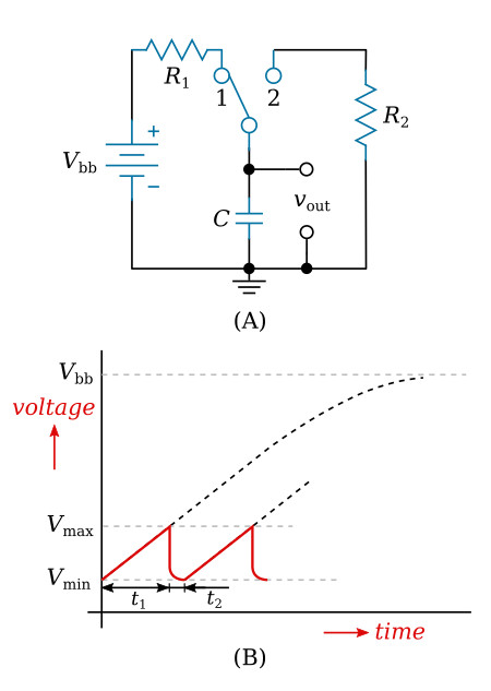
A basic sweep or sawtooth generating circuit is illustrated in the figure below. When the switch is placed in position 1 the capacitor charges through R1 toward Vbb (figure below, view A). When the voltage across the capacitor reaches some predetermined value, Vmax, the switch is thrown to position 2, discharging the capacitor through R2. Upon reaching a predetermined minimum value, Vmin (figure below, view B), the switch is returned to position 1 and the cycle repeats. Before considering more practical sweep circuits a closer examination of the circuit and waveforms of the figure below is in order. Note that what is being generated is a portion of an exponential charging curve. To achieve an essentially linear sweep, operation must be restricted to no more than the first ten percent of the total exponential charge curve. This portion of the curve, as shown in the figure below, view B, is nearly linear. The smaller the percentage of the total charging curve used, the better the linearity. Thus, Vbb must be made much greater than the desired output voltage swing (Vmax - Vmin) to ensure good linearity. The other option is to use a constant current source charging the capacitor. Also, note that the retrace time of the sawtooth (t2) is a function of the resistance of R2. Reducing R2 to a small enough value will cause the retrace time to be insignificant.
Ramp Generator with a Constant Current Source
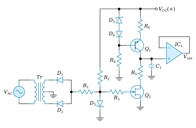
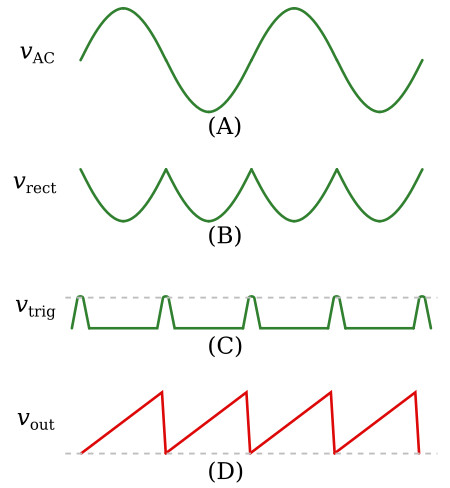
The figure above is a schematic of the linear ramp generator. The linear ramp is generated by capacitor C1 charging through constant current source, bipolar transistor Q1, while JFET transistor Q2 serves to synchronize its frequency. As indicated in the figure below, view A, a sample of the 60 Hz AC line voltage is applied through diodes D1 and D2. These two diodes act as a full wave rectifier to convert the line voltage to a negative going unipolar voltage vrect that pulsates at a 120 Hz rate. This pulsating voltage (figure below, view B) is then applied to the anode of Zener diode D3. The Zener action of diode D3 converts the pulsating voltage into trigger pulses. The biasing network consisting of VCC and resistor R2 shifts the DC level of the trigger pulses, which occur at a 120 Hz rate, before they are applied to the gate of transistor Q2 (figure below, view C). The pulses trigger transistor Q2 into conduction, rapidly discharging capacitor C1. As a result, capacitor C1 produces a 120 Hz, constant amplitude, positive ramp (shown in the figure below, view D) that is led through buffer IC1 to the output.