


Home > Textbooks > Basic Electronics > Operational Amplifiers > Block Diagram >
Operational Amplifiers
Block Diagram
Figure below is a block diagram of an operational amplifier. Notice that there are three stages within the operational amplifier.
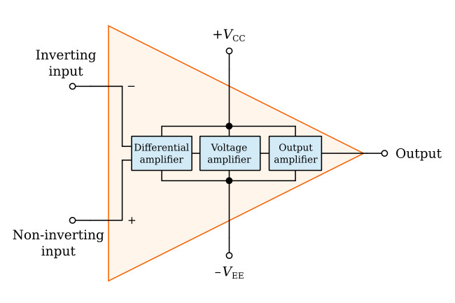
The input stage is a differential amplifier. The differential amplifier used as an input stage provides differential inputs and a frequency response down to DC. Special techniques are used to provide the high input impedance necessary for the operational amplifier.
The second stage is a high-gain voltage amplifier. This stage may be made from several transistors to provide high gain. A typical operational amplifier could have a voltage gain of 200,000. Most of this gain comes from the voltage amplifier stage.
The final stage of the opamp is an output amplifier. The output amplifier provides low output impedance. The actual circuit used could be an emitter follower. The output stage should allow the operational amplifier to deliver several milliamperes to a load.
Notice that the operational amplifier has a positive power supply (+VCC) and a negative power supply (−VEE). This arrangement enables the operational amplifier to produce either a positive or a negative output.
The two input terminals are labeled "inverting input" (−) and "noninverting input" (+). The operational amplifier can be used with three different input conditions (modes). With differential inputs (first mode), both input terminals are used and two input signals which are 180 degrees out of phase with each other are used. This produces an output signal that is in phase with the signal on the noninverting input. If the noninverting input is grounded and a signal is applied to the inverting input (second mode), the output signal will be 180 degrees out of phase with the input signal (and one-half the amplitude of the first mode output). If the inverting input is grounded and a signal is applied to the noninverting input (third mode), the output signal will be in phase with the input signal (and one-half the amplitude of the first mode output).


