


Home > Textbooks > Basic Electronics > Operational Amplifiers > Current to Voltage Converter >
Operational Amplifiers
Current to Voltage Converter
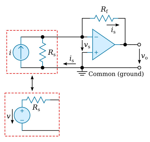
Figure above shows the basic configuration in which the operational amplifier (op-amp) is used as a current to voltage converter. In this diagram a real current source is represented by an ideal current source i with infinite impedance coupled with a finite impedance Rs in parallel. The equivalent voltage source is shown in the insert for ease of analysis. In this case the negative polarity input is tied to common (ground) so that the voltage drop across the op-amp inputs can be represented by vs. This configuration is called an "inverting circuit", since the polarity of the amplified signal will be changed. The properties mentioned above now imply that the output voltage is proportional to the open loop gain A according to the equation
![]()
and, since all the current is must flow through the feedback network because of infinite input impedance of the op-amp,

From the previous equations

and thus the input impedance of this circuit is

Hence in the case of infinite or near infinite gain (A -> ∞) the impedance is quite low, practically zero. The above equation also implies vs is approximately zero for finite signals is. Because of this well-known condition in which the signal input is practically at common potential (i.e. vs ≃ 0, virtual ground) and because the circuit input impedance is very low, this is an excellent device for measuring current sources. Note also that is = v/Rs = -vo/Rf for A -> ∞ implies the current is is independent of the feedback resistor Rf. Changing Rf alters vo, but has no effect on is.
In the case of infinite gain (A -> ∞) and nonzero Rs, the output voltage can be calculated as
![]()


