


Home > Textbooks > Basic Electronics > Operational Amplifiers > Integrator >
Operational Amplifiers
Integrator
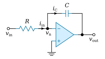
The figure below shows an integrator. The capacitor of this circuit connects the inverting input and the output signal points of the operational amplifier in such a manner that the output potential varies as the time integral of the input potential.
For a capacitor

where iC is the current through the capacitor, vC is the voltage across the plates, and C is the capacitance. The inverting input is at a virtual ground (vn = 0) and currents in the resistor and capacitor are equal (iin = iC). Application of Ohm's Law and substitution from the previous equation (iC = C dvC/dt) gives

Integrating both sides and rearranging gives

where v0 is the initial value of output voltage at time t = 0. For the moment assume that v0 has zero value, when,

where T = RC is the time constant of the integrator. This determines the amplitude scaling which is applied. The relation of the previous equation indicates that a voltage may be integrated with respect to time.


