


Home > Textbooks > Basic Electronics > Operational Amplifiers > Summing Amplifier >
Operational Amplifiers
Summing Amplifier
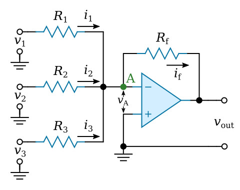
The process of adding and subtracting voltages is performed by a summing amplifier. The figure above shows an arrangement for the summation of three voltages v1, v2, and v3, applied to input resistors R1, R2, and R3 respectively.
The three input currents i1, i2, and i3 may be equated to the current if through Rf
![]()
The currents are equal to

Since vA is approximately equal to zero (the virtual ground), the currents which are added can be seen to be

The rearrangement of the equation gives

This equation tells us that each input voltage is multiplied by a gain determined by the value of its own input resistor and the common feedback resistor. In addition, each amplified input voltage is algebraically added to the other amplified input voltages. In the special case, when each resistance ratio is 1, the circuit merely algebraically adds all of the input voltages. Subtraction occur when the signs of some of the input voltages are negative. Note that the total algebraic sum of the input voltages is inverted by the operational amplifier.
Now let’s consider a few examples. Consider the summing amplifier circuit shown in the figure below. Input voltage v1 (+5 V) will have a gain of 1/2. Input voltage v2 (+3 V) will have a gain of 1. Input voltages of +5 V and +3 V will produce the following currents: current i1 = 2.5 μA and i2 = 3 μA (i.e. v1/R1 and v2/R2). The output voltage is then -ifRf or –5.5 V.
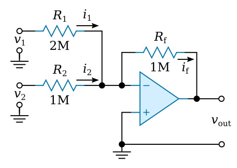
The circuit conditions under slightly different input voltages (v1 = -10 V, v2 = +3 V) are considered next. Note that current i1 flows in the opposite direction when v1 is negative. Under these conditions, i1 = -5 μA and i2 = 3 μA. The current which flows through Rf must be the sum of i1 and i2. This sum, -2 μA, flows through the feedback resistor and indicates an output voltage of +2 V.


