


Home > Textbooks > Selected Circuits > Tests and Measurements > Constant-Current Load Circuit >
Tests and Measurements
Constant-Current Load Circuit
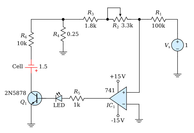
The circuit configuration for testing battery cell capacity is shown above. This setup provides a variable resistive load which draws a constant current from cell.
The constant-current load circuit was designed to provide a predictable discharge rate that is independent of the cell terminal voltage. The circuit features a ground-referenced current-sensing resistor (R4) to provide negative feedback to an inverting amplifier formed by an operational amplifier (741) driving a power transistor (2N5878). The base current to the power transistor is limited by resistor R5 and an LED (light emitting diode), which is mounted on the front panel and is visible to the test operator. The LED brightness increases considerably as a cell discharges and serves as a useful visual end-of-test indicator. The magnitude of the cell test current is determined by a voltage source Vs. The gain of the active devices in conjunction with the ratio R1/(R2 + R3) maintains a scaled version of the input voltage (Vs) across R4. Thus, the circuit maintains a load current that is proportional to the input voltage. The gain constant is adjusted by R2. The input voltage for the load circuit is derived from a voltage standard to ensure stability, resolution, and resetability of the load current.
