


Home > Textbooks > Selected Circuits > Tests and Measurements > Smoothly Adjustable DC Load >
Tests and Measurements
Smoothly Adjustable DC Load
A load circuit for testing DC power supplies can be adjusted without the momentary interruptions typical of rheostat loads. Load current passes through a power transistor and fixed resistor instead of through a wire-wound rheostat; it is therefore not subject to the interruptions that sometimes occur when a rheostat wiper skips from wire to wire during the adjustment of a load.
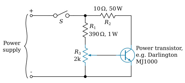
In the circuit, a 10-turn precision potentiometer (R3) is used to adjust the bias of the power transistor and thereby adjust the load. There is very little load current in the potentiometer, however.
The DC power supply to be tested is connected to the input terminals of the load circuit, and the on/off switch of the load circuit is closed (see the figure above). The load is adjusted by turning the potentiometer knob. When the knob is turned fully down, the transistor is biased off, and the load current is nearly zero. When the knob is turned fully up, the transistor is fully on, and the load current is at its maximum value. The 390-ohm fixed resistor (R1) in series with the potentiometer limits the bias current to a safe level when the potentiometer is at its highest setting. For a 10-ohm fixed load resistor R2 and a typical 28-VDC power supply, the maximum load current is 2.8 A. The maximum design load is limited by the power-dissipation ratings of the resistor and transistor selected for the circuit. Higher loads, of course, would be possible with components having higher ratings.
