


Home > Textbooks > Selected Circuits > Tests and Measurements > Pulse Width to Voltage Converter >
Tests and Measurements
Pulse Width to Voltage Converter
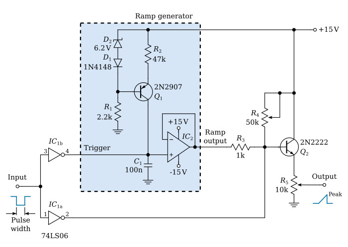
The circuit converts pulses of varying widths (as from sound-velocity instrumentation or tachometers) into analog voltages. The peak voltage increases in proportion to the pulse width. This voltage can be used, for example, to drive an x-y plotter or a storage oscilloscope.
The converter circuit (see figure) requires a ramp generator of the type that is turned on by a positive gating pulse and both turned off and reset to zero output when that gating pulse returns to zero. The input pulse from the instrumentation (which is actually an interruption of the otherwise-steady 5-Vdc input) is inverted by part of the 74LS06 integrated circuit (IC1b). The resulting positive pulse (output transistor of IC1b is open) serves as the ramp gate. Since the ramp voltage rises linearly with time, the peak ramp voltage just before shutoff is proportional to the duration of the input pulse.
The ramp voltage is fed to the output terminal through an emitter follower (Q2). The input pulse is also fed through one section of the 74LS06 inverting buffer (IC1a). This provides further control of the emitter-follower base by shorting it to ground when the input pulse is absent.
The emitter-follower output voltage includes a zero-pulse-width offset voltage that is adjusted by setting a 50-kΩ variable resistor. The proportionality between the ramp rise and the pulse width is determined by setting a 10-kΩ voltage divider, a typical calibration factor being about 1 volt per 1 ms.
Useful link:
74LS06 datasheet (pdf)
