


Home > Textbooks > Selected Circuits > Tests and Measurements > Peak/Average Detector >
Tests and Measurements
Peak/Average Detector
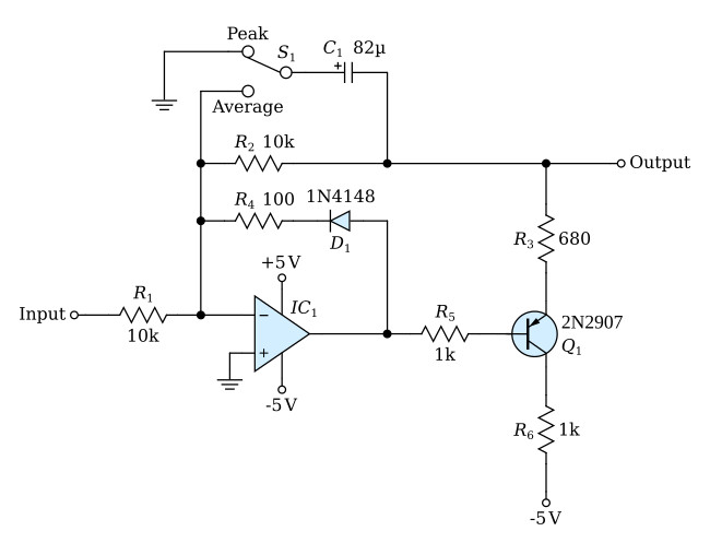
This circuit detects either peak or average of positive signals. The mode of operation can be switched by a single-pole, double-throw switch (S1 in the figure). The circuit can be used in automatic light-control systems for cameras, where the video output must be constant over large ranges of input light level.
The advantage of this circuit is that it does not require the conventional double-pole, double-throw switch. In addition, an operational amplifier (op-amp) with feedback makes the device precise and temperature stable. The detector is basically a unity-gain, inverting amplifier with feedback. Components shown in the figure, but not described, are used for biasing. R4 and D1 are used for suppressing negative input signals.
In the peak mode one side of capacitor C1 is grounded. When a positive-going signal is applied to the input, the other side of C1 is charged negatively by the op-amp through transistor Q1. The charging process stops when the output is the negative equivalent of the positive input peak. Between peaks the voltage on C1 decays through R2 and R1 and not through Q1, because Q1 emitter has no positive return. Thus Q1 acts as a rectifier. R3 sets the charge time so that when a minimum-width input pulse is received the circuit cannot detect it.
In the average mode, C1 is connected in parallel with the feedback resistor R2. Then the circuit acts as a low-pass filter, and the output is a DC potential equal to the input average.
A positive voltage return path for the emitter of Q1 is not necessary. This path is provided by R2 into the inverting input of the op-amp. The elimination of a positive voltage return for Q1 emitter makes the circuit unique. It allows Q1 to play a dual role: a rectifier in the peak mode, an emitter-follower in the average mode. Thus no additional switching is required at Q1. In addition, since the output of the detector is the feedback point, temperature variations in the emitter-base drop of Q1 are automatically compensated.
