


Home > Textbooks > Selected Circuits > Tests and Measurements > Matching of Diodes >
Tests and Measurements
Matching of Diodes
Two circuit arrangements, one using an AC and the other a DC power source, rapidly select diodes and other semiconductor devices with matched, forward voltage drops. Both circuits are simpler (and less expensive) than conventional, characteristic-curve tracers.
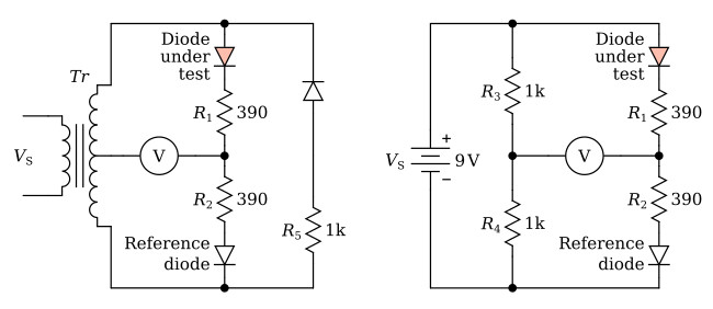
The AC and DC test circuits, which are bridge configurations, are shown in the figure above. Both versions include two precision equal-value current-limiting resistors R1 and R2 in the bridge legs containing the diodes. Each circuit also includes a voltmeter to detect bridge imbalance. The DC circuit has precision resistors in the other bridge legs, and the AC circuit includes an additional diode and resistor (R5) to prevent transformer core saturation during one-half of the AC cycle.
Throughout the tests, any difference in forward voltage drop between the test and the reference diodes is displayed as either a positive or negative voltage across the measuring device. After testing a batch of diodes, those with identical voltage offsets (within prescribed limits) are easily separated into groups for subsequent use in matched pairs.
For each test, the supply voltage and current can be fixed at levels identical to those encountered by the semiconductor in actual operation. This is controlled by selecting the correct value of R1 and R2. The figure above shows representative resistor values for testing signal diodes supplied by a 9-V source. Both power and signal diodes can be tested in the same arrangement.
