


Home > Textbooks > Selected Circuits > Tests and Measurements > I/V-Curve Tester >
Tests and Measurements
I/V-Curve Tester
The load-simulator circuit measures the current/voltage characteristics of power sources. Since low-power integrated circuits are used, a 9-volt battery could power the circuit for field use.
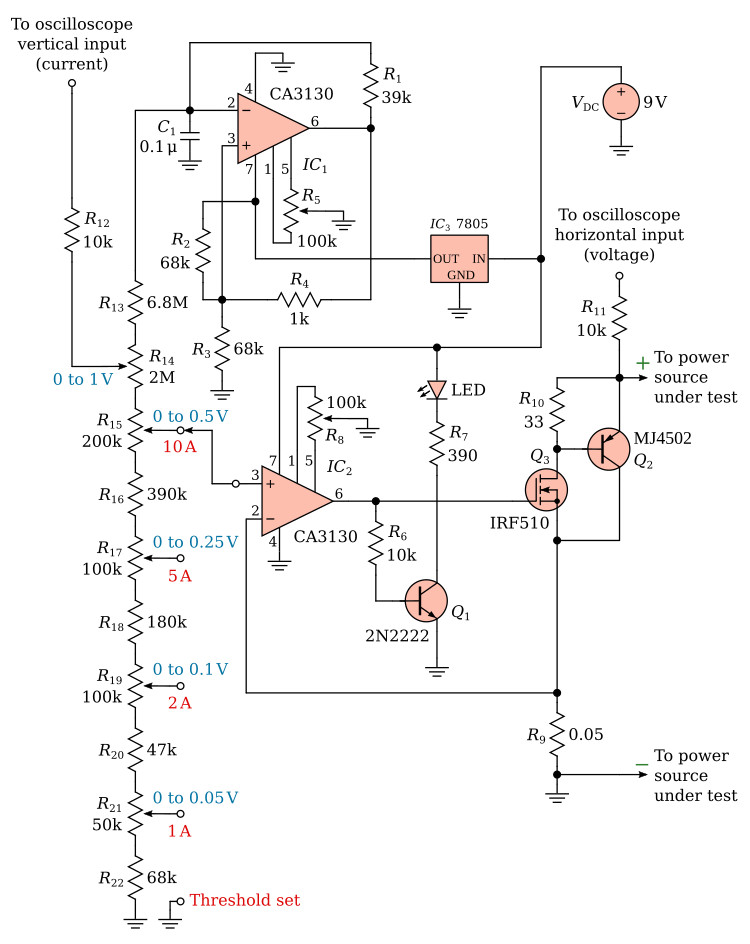
The circuit is shown in the figure above. Operational amplifier IC1 produces a nonideal triangle waveform. The triangle signal is proportional to, and is used to control, the current drawn from the power source being tested.
The triangle signal is also connected to the oscilloscope vertical input (current axis) through the adjustment potentiometer (R14). The horizontal axis (voltage axis) is across the power source through a 10-kΩ resistor. The triangle signal energizes a voltage divider to provide a control signal for the servo loop controlling the main load transistor Q2. A switch selects the tap corresponding to the desired current range, and a calibration adjustment potentiometer is provided for each tap.
Operational amplifier IC2 compares the triangle voltage to the voltage drop across the 0.05-Ω load-current sensing resistor. IC2 drives the gate of transistor Q3, which in turn drives the base of the main load transistor Q2. If the load current is lower than it should be at any moment, the voltage across the sensing resistor will be lower than the triangle voltage. This will cause the output of IC2 to go further positive, increasing the currents through Q3 and Q2 until the error is corrected.
An extra position on the range is used when adjusting the load threshold control (R8) so that the load current goes to zero when the triangle voltage goes to zero. The control is adjusted until the LED "load-on" indicator goes out. The circuit could be adapted for use with a slower display device, such as an X/Y recorder by increasing the value of the 0.1-µF integrating capacitor connected to the inverting input of IC1.
Useful links:
CA3130 datasheet (pdf)
MJ4502 datasheet (pdf)
