


Home > Textbooks > Selected Circuits > Tests and Measurements > Zero Phase Shift Indicator >
Tests and Measurements
Zero Phase Shift Indicator
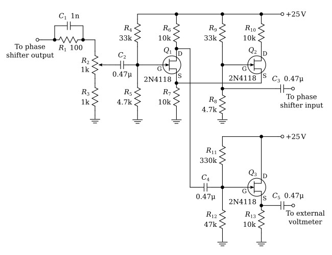
The figure above shows the circuit provided for indicating phase coincidence (zero phase shift) between the phase shifter input and output. This circuit can function as a calibrator of variable phase shifters. Phase coincidence is indicated by a voltage null read on a voltmeter driven by the circuit.
The circuit utilizes field effect transistors. Transistor Q3 functions as a source followers, and Q1 and Q2 forms a differential amplifier. A differential voltage appears at the load resistor in the drain of Q1 when simultaneous inputs are applied to the gate and source. The gate is driven by the phase shifter output, while the source input is taken from the phase shifter input via Q2. Gain adjustment of the gate voltage is provided by a 10-turn potentiometer R2. The differential voltage produced at the Q1 drain drives a source follower which provides an output to an external voltmeter.
The field effect transistor was selected because it is advantageous that the phase shifter input-output terminals remain isolated. The principal design requirement for correct indication of phase coincidence is that the gate and source channels introduce equal phase shifts throughout the operating frequency range. The phase shift in the gate channel tends to be larger at the higher frequencies because of the Q1 gate capacitance to ground. Correction for the difference in capacitance is made with a load network (100 ohms in parallel with 1 nF) in the gate circuit of Q1. Compensation is achieved over a frequency range from 1 kHz to 700 kHz; imperfect compensation is indicated by a variation in the null with frequency when both inputs are driven from a constant voltage, common source.
For a minimum null, it will be necessary to adjust the phase shifter output gain control; fine gain adjustment is provided by the 10-turn potentiometer in the Q1 gate circuit of the differential amplifier. Imperfect gain adjustment decreases the sensitivity to phase change, but does not cause an error; the null will always correspond to the in-phase condition. Further, nulls occur only at zero degree or integral multiples of 360 degrees. Sensitivity is such that with 0.5 volt at the phase shifter input and output terminals, the in-phase null will be roughly 5 mV; a 1-degree phase change from coincidence will produce an increment of 5 mV.
Useful link:
2N4118 datasheet (pdf)
