


Home > Textbooks > Basic Electronics > Wave Shaping > Limiters >
Wave Shaping
Limiters
A limiter is defined as a device which limits some part of a waveform from exceeding a specified value. Limiting circuits are used primarily for wave shaping and circuit-protection applications.
By using a diode, a resistor, and sometimes a DC bias voltage, you can build a limiter that will eliminate the positive or negative alternations of an input waveform. Such a circuit can also limit a portion of the alternations to a specific voltage level. In this section you will be introduced to five types of limiters: series-positive, series-negative, parallel-positive, parallel-negative, and dual-diode limiters.
The diode in these circuits is the voltage-limiting component. Its polarity and location, with respect to ground, are the factors that determine circuit action. In series limiters, the diode is in series with the output. In parallel limiters, the diode is in parallel with the output.
Series Limiters
The diode will conduct when the anode voltage is positive with respect to the cathode voltage. The diode will not conduct when the anode is negative in respect to the cathode. Keeping these two simple facts in mind as you study limiters will help you understand their operation. The knowledge of voltage divider action will also help you understand limiters.
In a series limiter, a diode is connected in series with the output, as shown in view (A) of the figure below. The input signal is applied across the diode and resistor and the output is taken across the resistor. The series-limiter circuit can limit either the positive or negative alternation, depending on the polarity of the diode connection with respect to ground. The circuit shown in figure below, view (A), is a series-positive limiter. Reversing D1 would change the circuit to a series-negative limiter.
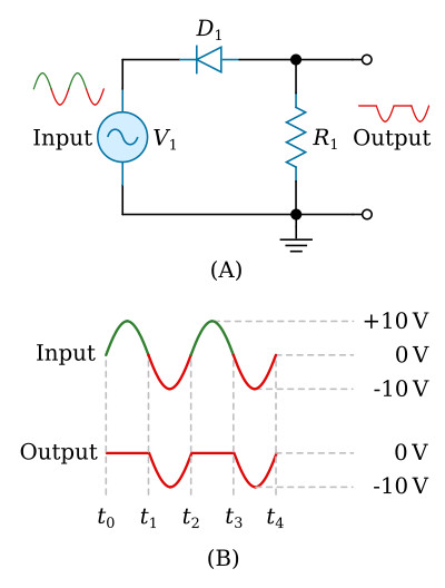
Series-Positive Limiter
Let's look at the series-positive limiter and its outputs in the figure above. Diode D1 is in series with the output and the output is taken across resistor R1. The input must be negative with respect to the anode of the diode to make the diode conduct. When the positive alternation of the input signal (t0 to t1) is applied to the circuit, the cathode is positive with respect to the anode. The diode is reverse biased and will not conduct. Since no current can flow, no output is developed across the resistor during the positive alternation of the input signal.
During the negative half cycle of the input signal (t1 to t2), the cathode is negative with respect to the anode. This causes D1 to be forward biased. Current flows through R1 and an output is developed. The output during each negative alternation of the input is approximately the same as the input because most of the voltage is developed across the resistor. The actual amount of voltage developed across the diode will depend on the type of diode used. For the remainder of this section, we will use only idealized waveforms and disregard this small voltage across the diode.
Series-Positive Limiter with Bias
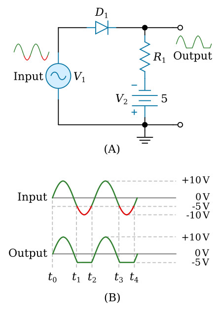
In the series-positive limiter (figure above, view (A)), the reference point at the bottom of resistor R1 is ground, or 0 volts. By placing a DC potential in the figure below (view (A)), you can change the reference point. The reference point changes by the amount of DC potential that is supplied by the battery. The battery can either aid (positive bias) or oppose (negative bias) the flow of current in the series-limiter circuit.
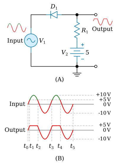
Let's look at a series-positive limiter with positive bias as shown in the figure above, views (A) and (B). The diode will conduct until the input signal exceeds +5 at t1 on the positive alternation of the input signal. When the positive alternation exceeds +5 volts, the diode becomes reverse biased and limits the positive alternation of the output signal to +5 volts. This is because there is no current flow through resistor R1 and battery voltage is felt at output. The diode will remain reverse biased until the positive alternation of the input signal decreases to just under +5 volts at t2. At this time, the diode again becomes forward biased and conducts. The diode will remain forward biased from t2 to t3. During this period the negative alternation of the input is passed through the diode without being limited. From t3 to t4 the diode is again reverse biased and the output is again limited.
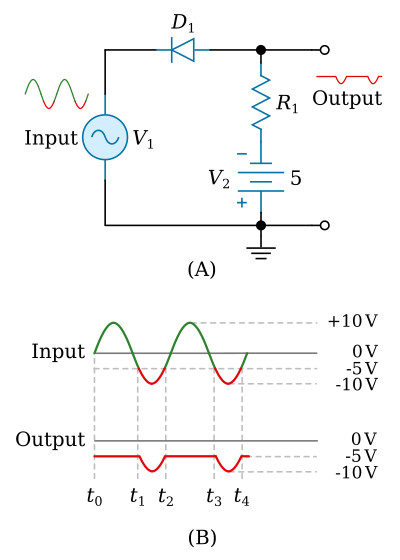
Now let's look at a series-positive limiter with negative bias as shown in the figure below, view (A). The diode is negatively biased with -5 volts from the battery. In view (B), compare the output to the input signal applied. From t0 to t1 the diode is reverse biased and limiting takes place. The output is at -5 volts (battery voltage) during this period. As the negative alternation increases toward -10 volts (t1), the cathode of the diode becomes more negative than the anode and is forward biased. From t1 to t2 the input signal is passed to the output. The diode remains forward biased until the negative alternation has decreased to −5 volts at t2. At t2 the cathode of the diode becomes more positive than the anode, and the diode is again reverse biased and remains so until t3.
Series-Negative Limiter
In view A of the figure below, the series-negative limiter limits the negative portion of the waveform, as shown in view B. Let's consider the input signal and determine how the output is produced. During t0 to t1 (view B), the anode is more positive than the cathode and the diode conducts. Current flows through the resistor and the diode, and a positive voltage is developed at the output. The voltage across the resistor is essentially the same as the voltage applied to the circuit.
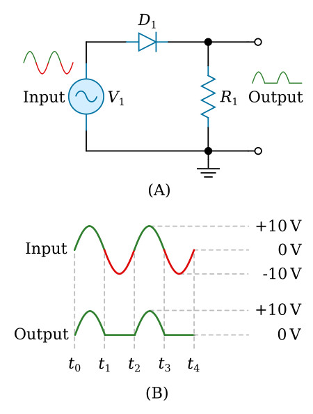
During t1 to t2 the anode is negative with respect to the cathode and the diode does not conduct. This portion of the output is limited because no current flows through the resistor.
As you can see, the only difference between series-positive and series-negative limiters is that the diode is reversed in the negative limiters.
Series-Negative Limiter with Bias
View A of the figure below shows a series-negative limiter with negative bias. The diode is forward biased and conducts with no input signal. In view B it will continue to conduct as the input signal swings first positive and then negative (but only to −5 volts) from t0 through t1. At t1 the input becomes negative with respect to the −5 volt battery bias. The diode becomes reverse biased and is cutoff until t2 when the anode again becomes positive with respect to the battery voltage (−5 volts) on the cathode. No voltage is developed in the output by R1 (no current flow) and the output is held at −5 volts from t1 to t2. With negative bias applied to a series-negative limiter, only a portion of the negative signal is limited.
Now let's look at a series-negative limiter with positive bias, as shown in the figure below, view A. Here we will remove all of the negative alternation and part of the positive alternation of the input signal. We have given a full explanation of the series-positive limiter, series-positive limiter with bias, series-negative limiter, and series-negative limiter with negative bias; therefore, you should have little difficulty understanding what is happening in the circuit in the figure.
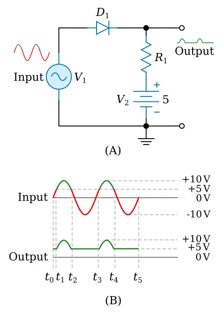
The series-negative limiter with positive bias is different in only one aspect from the series-positive limiter with bias discussed earlier. The difference is that the diode is reversed and the output is of the opposite polarity.


