Home > Textbooks > Basic Electronics > Wave Shaping > Shaping Circuits >
Wave Shaping
Shaping Circuits
Timing circuits and circuits which require a particular shape or "spike" of voltage, may use shaping circuits. Shaping circuits can be used to cause wave shapes, such as square waves, sawtooth waves, and trapezoidal waves, to change their shape. Shaping circuits may be either series RC or series RL circuits. The time constant is controlled in respect to the duration of the applied waveform. Notice that the wave shapes mentioned did not include the sine wave (thus they are called nonsinusoidal waves). These RC or RL shaping circuits do not change the shape of a pure sine wave.
The series RC and RL circuits electrically perform the mathematical operations of integration and differentiation. Therefore, the circuits used to perform these operations are called integrators and differentiators. These names are applied to these circuits even though they do not always completely perform the operations of mathematical integration and differentiation.
Composition of Nonsinusoidal Waves
Pure sine waves are basic wave shapes from which other wave shapes can be constructed. Any waveform that is not a pure sine wave consists of two or more sine waves. Adding the correct frequencies at the proper phase and amplitude will form square waves, sawtooth waves, and other nonsinusoidal waveforms.
A waveform other than a sine wave is called a complex wave. You will see that a complex wave consists of a fundamental frequency plus one or more harmonic frequencies. The shape of a nonsinusoidal waveform is dependent upon the type of harmonics present as part of the waveform, their relative amplitudes, and their relative phase relationships. In general, the steeper the sides of a waveform, that is, the more rapid its rise and fall, the more harmonics it contains.
The sine wave which has the lowest frequency in the complex periodic wave is referred to as the fundamental frequency. The type and number of harmonics included in the waveform are dependent upon the shape of the waveform. Harmonics have two classifications — even numbered and odd numbered. Harmonics are always a whole number of times higher than the fundamental frequency and are designated by an integer (whole number). For example, the frequency twice as high as the fundamental frequency is the second harmonic (or the first even harmonic).
View A of the figure below compares a square wave with sine waves. Sine wave K is the same frequency as the square wave (its fundamental frequency). If another sine wave (L) of smaller amplitude but three times the frequency (referred to as the third harmonic) is added to sine wave K, curve M is produced. The addition of these two waveforms is accomplished by adding the instantaneous values of both sine waves algebraically. Curve M is called the resultant. Notice that curve M begins to assume the shape of a square wave. Curve M is shown again in view B.
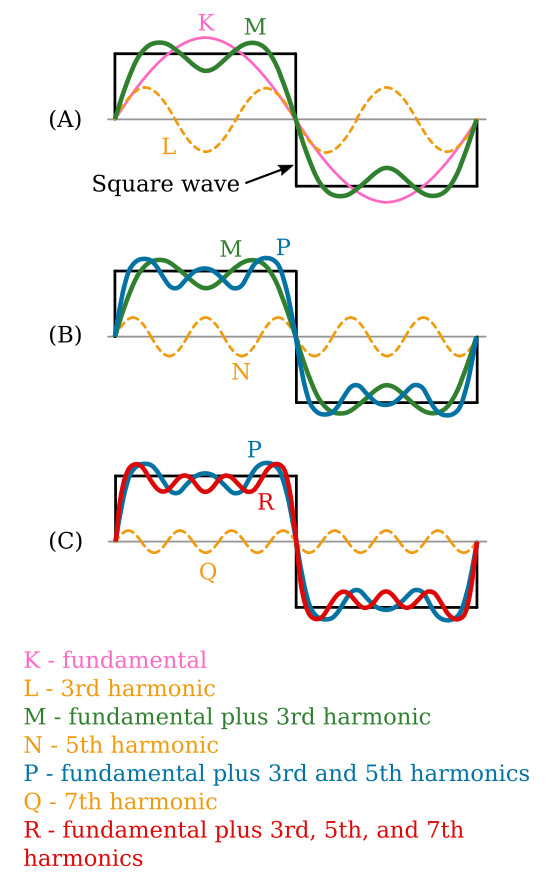
As shown in view B, when the fifth harmonic (curve N with its decreased amplitude) is added, the sides of the new resultant (curve P) are steeper than before. In view C, the addition of the seventh harmonic (curve Q), which is of even smaller amplitude, makes the sides of the composite waveform (R) still steeper. The addition of more odd harmonics will bring the composite waveform nearer the shape of the perfect square wave. A perfect square wave is, therefore, composed of an infinite number of odd harmonics. In the composition of square waves, all the odd harmonics cross the reference line in phase with the fundamental.
Nonsinusoidal Voltages Applied to an RC Circuit
The harmonic content of a square wave must be complete to produce a pure square wave. If the harmonics of the square wave are not of the proper phase and amplitude relationships, the square wave will not be pure. The term pure, as applied to square waves, means that the waveform must be perfectly square.
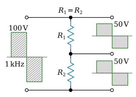
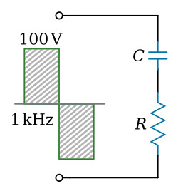
The figure above shows a pure square wave that is applied to a series-resistive circuit. If the values of the two resistors are equal, the voltage developed across each resistor will be equal; that is, from one pure square-wave input, two pure square waves of a lower amplitude will be produced. The value of the resistors does not affect the phase or amplitude relationships of the harmonics contained within the square waves. This is true because the same opposition is offered by the resistors to all the harmonics presented. However, if the same square wave is applied to a series RC circuit, as shown in the figure below, the circuit action is not the same (see the next section).